

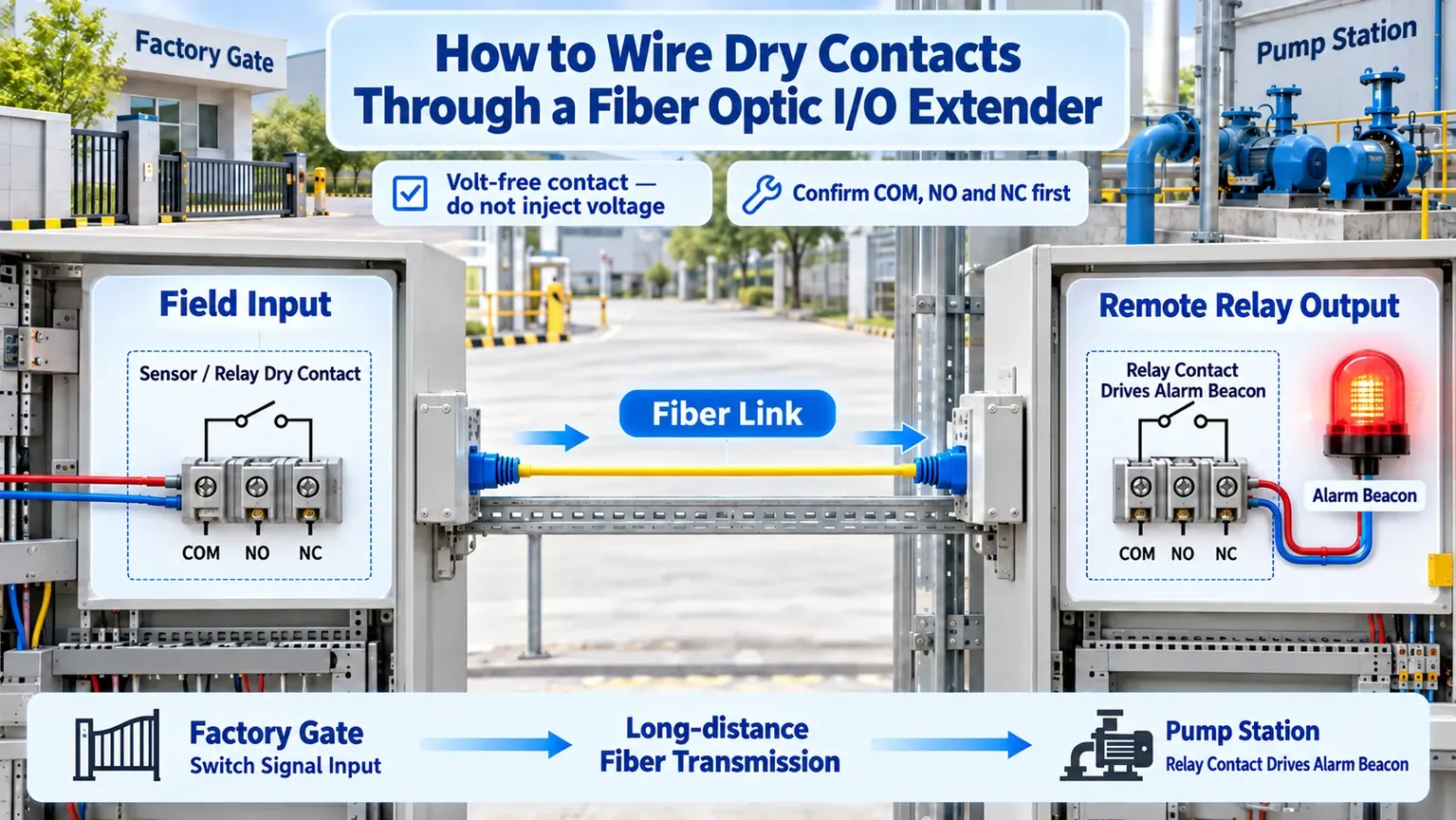
To wire a dry contact through a fiber optic I/O extender, first prove that the field signal is a volt-free contact. Then connect COM to either NO or NC according to the required normal state, carry the state across the fiber link, and verify the remote relay with a continuity test. Never inject an external voltage into an input that is specified for dry-contact operation. Terminal assignments, channel direction, relay ratings and power arrangements vary by model, so the product label and manual always take precedence over this general procedure.
01Start by identifying the signal type
A dry contact is only an electrically isolated switch state. It does not provide its own voltage. Door contacts, float switches, pressure-switch auxiliary contacts, fire-alarm relay outputs and motor-starter auxiliary contacts often work this way. In the normal state, the contact is either open or closed; when the process changes, the contact changes state. A wet contact is different because the field device presents voltage or current. That difference must be resolved before any conductor is landed.
The safest method is to disconnect the signal from the destination, follow the site isolation procedure, and measure the field terminals with an appropriate meter. A dry contact should behave as an open or closed circuit and should not present an external control voltage. If voltage is present, identify the source, polarity, common reference and range. Do not assume that a two-wire signal is dry merely because it uses two conductors.
At the remote end, many fiber I/O extenders provide a relay dry-contact output. The relay reproduces the state, but it does not automatically power a beacon, contactor or PLC input. The load circuit may require its own supply, fuse, intermediate relay and surge suppression. The FCTEL Digital Input/Output over Fiber product family is the relevant product direction; the actual input mode, output technology, channel count and ratings must be confirmed for the selected unit.
02Understand COM, NO and NC before wiring
COM is the common terminal. NO means normally open: COM and NO are open when the relay is in its normal or de-energized state and close when it operates. NC means normally closed: COM and NC are closed in the normal state and open when the relay operates. “Normal” describes the relay state, not necessarily the healthy process state, so the control narrative must define what the monitoring system expects.
For example, a gate may use COM and NO if the alarm is required only after the gate contact operates. A pump-failure loop may use COM and NC so that an open circuit can indicate either an alarm or a broken wire. This fail-safe approach can improve fault visibility, but it also means the PLC or alarm logic must distinguish a process trip from cable damage, loss of transmitter power or removal of a terminal. Where that distinction matters, use a separate health channel or supervised circuit.
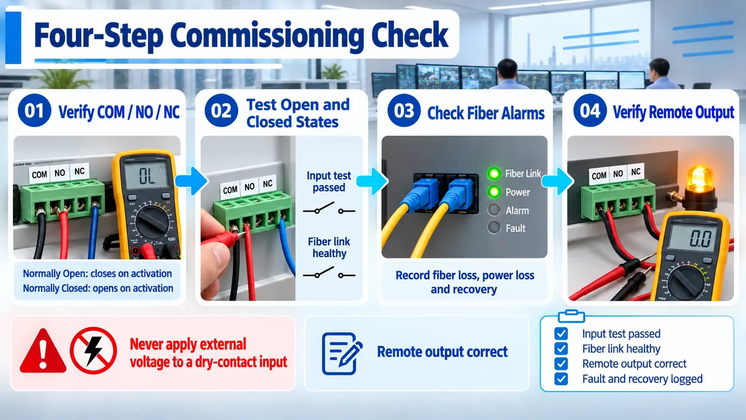
Before connecting the optical extender, operate the field device and record the continuity between COM–NO and COM–NC in both states. Label the conductors by function, not only by color. If the site drawing disagrees with the measurement, stop and resolve the discrepancy rather than “trying” terminals on a live system.
03Wire the local and remote ends in a controlled sequence
First, isolate the relevant control and load circuits, photograph the existing termination and record terminal numbers. Second, verify the local input terminal block and channel direction. Some systems are unidirectional; others provide bidirectional contact channels. Third, land the field dry contact on the specified input pair, using COM with NO or NC as required by the circuit design. Do not add an external supply unless the product documentation explicitly calls for a powered input.
Next, connect the fiber link. Confirm whether the pair uses one fiber or two, whether single-fiber units require complementary A/B wavelengths, and whether Tx/Rx orientation matters. Clean connectors before insertion, respect bend radius, and avoid judging link quality only from visible light or a single LED. If the product has a loss-of-signal indication, record its state before and after the link is connected.
Finally, wire the remote relay output into the PLC digital input, alarm loop or intermediate relay. Check the load voltage, current, AC/DC type and inrush characteristics against the selected unit’s documented output rating. Inductive loads such as contactor coils require appropriate suppression. High-current or mains loads should be switched by a correctly rated intermediate device rather than directly by a small signal relay.
04Troubleshoot from the contact outward
If the field contact changes but the remote output does not, start at the source. Measure continuity at the local terminal, then observe the corresponding input indication. If the input does not change, investigate the sensor contact, conductor pair, loose terminal, wrong COM reference or an unexpected powered signal. If the input changes correctly, move to the optical layer and check loss-of-signal alarms, connector cleanliness, A/B pairing, Tx/Rx orientation and received optical conditions.
When the fiber link is healthy, verify one-to-one channel mapping. A common commissioning error is to operate input 1 while measuring output 2, particularly on high-channel-count equipment. At the remote relay, measure COM–NO and COM–NC directly. If the relay changes correctly but the beacon or PLC does not, the fiber system has probably completed its task; continue with the remote supply, fuse, common reference, output wiring and destination input logic.
Intermittent operation needs a different approach. Check for contact bounce, corrosion, long unshielded field wiring, induced voltage, unstable device power and loose terminals. Log the local input LED, optical alarm and remote output at the same time. Repeatedly shorting unknown terminals is not a diagnostic method and can damage equipment. Energized testing must follow the site’s electrical safety procedure and be performed by qualified personnel.
05Commission normal, fault and recovery states
A successful point-to-point test is necessary but not sufficient. Begin with the link in its normal condition and operate the field contact at least three times. For each operation, record the local input state, optical-link state, remote relay state and final PLC or alarm indication. This confirms both signal mapping and the expected NO/NC logic.
Then disconnect the fiber in a maintenance window. Confirm the local and remote loss-of-signal indications, the relay’s fail state and the alarm presented to the control system. Reconnect the fiber and verify automatic recovery without a false latched state. Repeat the exercise for loss of power at the local unit and at the remote unit. The design should document whether the output releases, holds or enters another defined state during each failure.
For a critical pump, access-control or safety-related alarm, the responsible system engineer must approve the fail state. A fiber I/O extender can transmit contact information, but it does not by itself create a safety-rated loop. Functional safety, emergency shutdown and fire-alarm circuits require their own architecture, approved equipment and validation process.
06Use a repeatable acceptance record
| Item | What to record | Pass condition |
|---|---|---|
| Field contact | Dry/wet type, COM/NO/NC, normal and operated state | Measured state matches the control narrative |
| Channel mapping | Local input number and remote output number | Every point is mapped one to one |
| Fiber link | Fiber type, A/B or Tx/Rx orientation, alarms | Stable link with no unexplained alarm |
| Remote load | Supply, fuse, relay terminals and destination input | Load operates without exceeding documented limits |
| Failure tests | Fiber loss, local power loss, remote power loss and recovery | Defined fail state and repeatable recovery |
Store the record with the terminal drawing, fiber identifier, product name, ordered configuration and firmware or hardware revision when applicable. Those details prevent a future replacement from being wired according to a visually similar but electrically different unit.
07Define the product boundary before selection
Channel count is only the first selection question. Also confirm whether the input expects a dry contact or powered signal, whether the output is an electromechanical relay or solid-state device, whether transmission is one-way or bidirectional, and whether the installation requires DIN-rail or rack mounting. Power input, optical interface, operating environment, isolation, surge protection and alarm outputs must be matched to the site.
If the project also needs Ethernet, serial data, audio or voice, a multi-service fiber multiplexer may reduce the number of fibers and chassis. If the project carries only a small number of alarm contacts, a dedicated digital I/O-over-fiber device can be easier to test and maintain. Combining services should never obscure who owns each signal or how a single equipment failure affects multiple applications.
Engineering boundary: This article explains a general dry-contact workflow. It does not claim that every FCTEL model has COM, NO and NC on both ends, accepts the same input circuit, or supports the same relay load. Always use the terminal definition and electrical ratings for the exact ordered configuration.
08Maintenance practices that prevent repeat faults
During routine maintenance, operate representative contacts, inspect terminal torque, review optical alarms and compare the current state with the acceptance baseline. Clean fiber connectors with approved materials and protect unused adapters. A link that recovers after reseating may still have contamination, excessive loss or mechanical stress and should not be closed without evidence.
When a user reports that “the remote alarm does not work,” follow the same boundary sequence every time: identify dry or wet input, prove contact operation, verify local channel indication, verify the fiber link, measure the remote relay, and then test the load circuit. This sequence is faster and safer than replacing both endpoint units without knowing which layer failed.
For related optical-link fundamentals, see FCTEL’s Digital Input/Output product area and the broader Technical Articles library. Use descriptive project labels so that future maintenance staff can trace the field contact, fiber core and remote relay without relying on memory.
