

FCTEL / FIELD WIRING GUIDE
Terminate the two physical ends of each RS-485 electrical segment.
Place the resistor across A and B at each endpoint. For a cable with about 120 Ω differential characteristic impedance, one approximately 120 Ω termination at each end is common. Confirm built-in termination first; the actual value and settings follow the cable and device documentation. Intermediate nodes normally remain un-terminated, and biasing serves a different purpose.
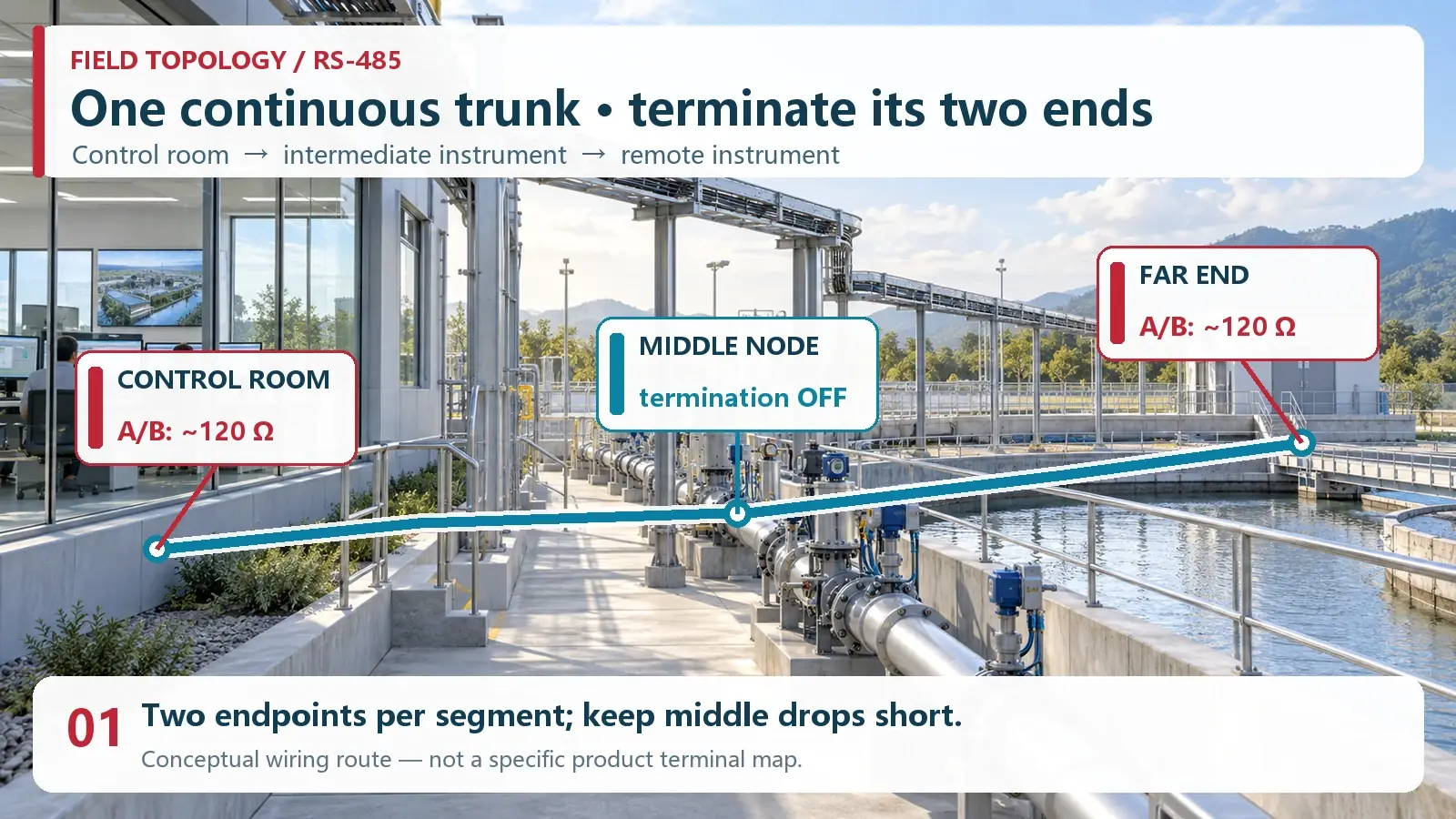
01Find the two physical ends of the segment
Start with the wiring route rather than a list of device addresses. A conventional two-wire, half-duplex RS-485 segment has a main twisted-pair trunk. The controller, serial server, gateway, meter and remote I/O nodes attach along that trunk. Termination belongs at the two most distant electrical ends of the continuous cable, not at the first and last devices shown on a software screen. A node in the middle should normally leave its termination disabled. Keep drops from the trunk short because a long branch creates another reflection path.
A star arrangement is not repaired by adding a 120-ohm resistor to every branch. Doing so can overload a driver while leaving the cable geometry that caused the problem untouched. If a facility already has long branches, assess a suitable repeater or hub and treat each isolated output as a separate segment. Determine the two endpoints again on each new electrical segment. The FCTEL 4-Port Opto-Isolated RS485 Hub/Repeater is one real product direction for segmenting field wiring. Its product page describes a built-in 120-ohm matching resistor on the A terminal; confirm the particular port arrangement, switch setting, and current documentation before design or installation.
02Choose the resistor for the cable, not by habit
The purpose of end termination is to make the line end resemble the differential characteristic impedance of the cable. Reflections caused by an impedance discontinuity can distort a received bit, especially as cable length, edge speed and data rate increase. Industrial twisted-pair cable is often specified around 120 ohms, which explains the familiar recommendation of about 120 ohms across A and B at each end. A different cable or integrated termination network may require a different arrangement. Read the cable data sheet and the equipment manual before applying a generic value.
Two 120-ohm resistors at opposite ends appear as roughly 60 ohms in parallel when measured across A and B on an isolated, de-energized segment. That is a useful sanity check, not an absolute acceptance number. Receiver input resistance, bias circuits, protective components, switched branches and other connected equipment can alter the meter reading. Never use the resistance range on a live circuit. Isolate the segment, verify the absence of external voltage, and follow the site’s electrical test procedure.
Short, low-speed networks may seem to work without termination. That does not prove the layout is robust when another meter is added or a noisy motor starts. Conversely, adding resistors to every fault does not fix reversed conductors, a wrong serial format or a missing master request. Decide from the physical topology and signal behavior, then test the complete communication path.
03Check built-in termination before adding anything
Many controllers, serial servers and repeaters contain a termination network enabled by a DIP switch, jumper or configuration option. Some have a fixed resistor. A technician may see no external resistor and assume the line is unterminated even though the electrical load is already present. Walk the route, read each port’s documentation and record the switch position. If the physical endpoint has an active built-in terminator, do not place another 120-ohm resistor across the same terminals without a documented reason.
Multiple parallel terminations lower the effective differential load and may reduce signal amplitude. The opposite mistake is leaving the old endpoint terminated after a plant extension makes it a middle node. Change the endpoint map whenever an instrument moves, a branch becomes a trunk, or a repeater is installed. Put the new setting in the wiring drawing, not just in a commissioning notebook.
04Keep bias, polarity and grounding separate
Termination and fail-safe bias do different jobs. Termination controls reflections at a cable end. Bias establishes a defined idle state when nobody drives the bus, unless the transceiver provides adequate internal fail-safe behavior. An external bias network, if the design calls for one, normally has an identified location and calculated values. It is not simply another 120-ohm resistor. Repeating bias at every node can create an excessive load or conflicting references.
A/B naming is not entirely consistent across product families. Do not assume that matching letters across two vendors guarantees matching differential polarity. Check the manual’s definition or validate with a known test frame. The shield, signal reference conductor and protective earth also have distinct purposes. Their connection strategy depends on isolation and the site’s grounding plan. Swapping A/B or adding a terminator cannot correct a severe common-mode voltage or an earth-loop problem.
At a gateway or serial server, physical-layer success is only one condition for useful data. The master/slave role, baud rate, parity, stop bits and application address must match the field instrument. For Modbus RTU, a valid electrical waveform can still yield a timeout if the unit ID, function code or register map is wrong. Keep physical and protocol evidence separate in the fault record.
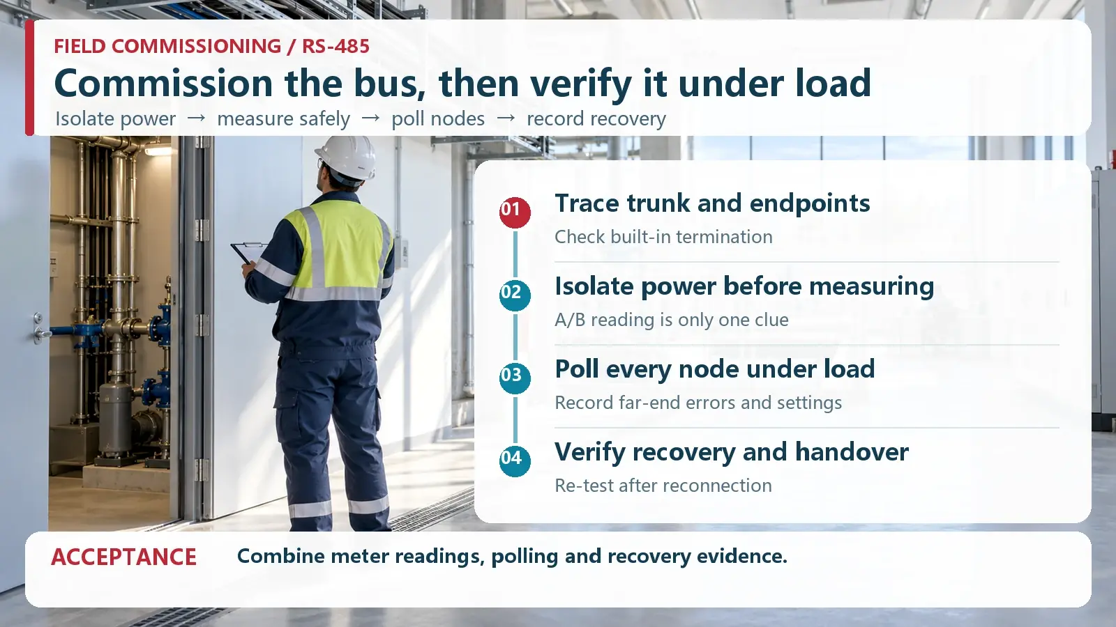
05Commission the whole segment
First, mark the trunk, both endpoints, every drop, cable type and equipment port. Photograph each built-in termination switch. With the segment de-energized and isolated, check continuity and resistance across A/B, and look for shorts to power or chassis where the design does not call for them. Restore power only after the wiring review is complete. Observe idle conditions and the controller’s communication indicators.
Next, poll each device with the intended serial format and application protocol. Record unit addresses, response values, timeouts, frame errors and retries. Include the most distant node and a representative operating load. If the problem appears only during motor starts, welding, or a change in network traffic, capture those conditions rather than relying on a quiet bench test. Where suitable instruments and qualified personnel are available, compare the differential waveform at the near and far ends for overshoot, ringing and margin.
Finally, introduce a controlled failure in a maintenance window: open the remote end, remove one device, or restart the upstream serial gateway. Verify that alarms occur as expected and that polling resumes without stale values or duplicate records. A system that works only until the first restart is not ready for acceptance. Record the restoration procedure so the next technician can reproduce it.
Where several teams share the installation, identify who owns the cable, serial parameters, gateway configuration and application point list. Repeat the test after a cabinet relocation or instrument replacement, even if the new hardware appears identical. A change in built-in termination, input protection or transceiver fail-safe behavior can alter the segment load. Keep before-and-after error counters and a short packet capture or poll log; these provide a stronger comparison than an operator’s impression that the screen looks normal.
06Troubleshoot in layers
| Symptom | First checks | Evidence to retain |
|---|---|---|
| All nodes silent | Power, master request, A/B polarity, serial format, common reference | Measured supply and a captured request frame |
| Only distant nodes fail | Endpoints, duplicate termination, long drops, cable condition | Trunk drawing, switch positions and error trend |
| Intermittent errors | Noise source, loose terminals, grounding, bias and load | Time-correlated errors and operating conditions |
| Frames received but data wrong | Unit ID, function code, register map, scaling and byte order | Raw request/response and instrument documentation |
A missing response does not automatically prove that termination is absent. Work from power and wiring toward physical signaling and then the application protocol. For a related diagnostic workflow, see FCTEL’s technical article library. Select a repeater, fiber converter or serial server only after identifying the problem it is meant to solve. A fiber span can isolate or extend communication, but the electrical RS-485 segment on either side still needs its own endpoint assessment.
07Hand over a reproducible record
The acceptance package should state the two endpoint locations, cable type, trunk and drop routes, termination values or switch positions, bias source, A/B convention, serial settings, device addresses and test date. Include a normal-state poll, a loaded poll, a deliberate fault and a recovery result. Keep the FCTEL model and revision with the record when a FCTEL device is used. This prevents a visually similar replacement unit from inheriting an incorrect terminal assumption.
Use the device manual and project drawings for final values and safety rules. This guide explains the engineering decision about where termination belongs; it does not claim that every RS-485 network needs the same resistor value or that one resistor can compensate for an unsuitable topology. A maintained endpoint map and repeatable evidence are the real goal.
