


FCTEL Original Technical Article · FCTEL Technical Team
First published: 2026-10-08 · Last modified: 2026-10-08
A PLC cable is connected and the switch link LED is on, yet the HMI still cannot reach it. A working physical link establishes signal transmission; an IPv4 endpoint also needs the Ethernet address of its next hop. ARP maps a local IPv4 address to a MAC address. Following the actual request-processing sequence explains address resolution, cache updates and the mechanism behind duplicate-IP faults.
Open the original image for detail. Scroll horizontally to read the diagram labels at full size.
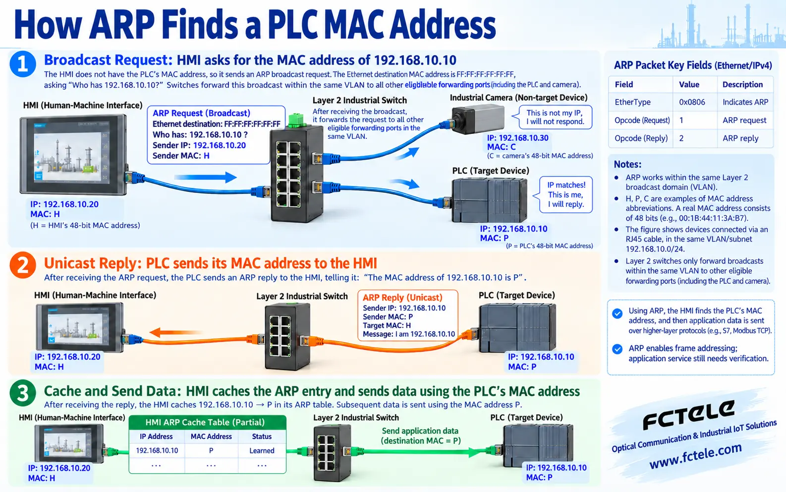
Choose the next hop before sending a business frame
IP addresses provide network-layer addressing; MAC addresses identify the destination at the Ethernet link layer. An Ethernet interface normally uses a 48-bit MAC address, and a switch uses that address to select an output port. Configuring a PLC IP address does not mean the HMI already knows its MAC. A lit link LED does not prove that addressing or the application service is correct.
Assume an HMI at 192.168.10.20/24 and a PLC at 192.168.10.10/24 in the same VLAN. The /24 prefix means the first 24 bits identify the network, equivalent to mask 255.255.255.0. The HMI consults its routing table, identifies the PLC as a directly connected destination and checks its own ARP cache. All addresses and abbreviated MAC labels in this article are teaching examples, not FCTEL field measurements.
For a destination such as 192.168.20.10, the HMI will normally use a gateway such as 192.168.10.1. It resolves the local gateway MAC, rather than the remote PLC MAC. The frame destination MAC belongs to the gateway while the packet destination IP still belongs to the remote PLC. A router creates a new Ethernet encapsulation on the next link. MAC addresses can therefore change at each hop while ordinary routing preserves the final destination IP.
Broadcast the question and unicast the answer
Without a usable cache entry, the HMI sends an ARP request. The Ethernet destination is the broadcast MAC FF:FF:FF:FF:FF:FF, and EtherType 0x0806 identifies an ARP payload. For Ethernet and IPv4, the ARP header commonly specifies hardware type 1, protocol type 0x0800, hardware-address length 6, protocol-address length 4, an operation code and sender and target addresses. The request operation is 1; the reply operation is 2.
The request includes the HMI IP and MAC and asks which device owns 192.168.10.10. The target hardware address is not yet known and is normally zero in the request. The switch copies the broadcast to other eligible forwarding ports in that VLAN, rather than to every VLAN. An unrelated camera normally does not answer; the PLC recognizes its own target IP and prepares a reply.
An ordinary reply is unicast to the HMI and supplies the PLC sender IP and MAC. The HMI can then map 192.168.10.10 to that MAC and encapsulate its waiting business frame. Address discovery requires a broadcast, but each subsequent business packet does not. Retries, timeouts and cache aging depend on the endpoint implementation; one fixed timer cannot describe every PLC, computer and gateway.
Open the original image for detail. Scroll horizontally to read the diagram labels at full size.
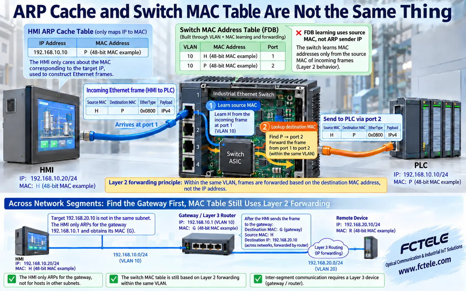
Keep the endpoint ARP cache separate from the switch MAC table
An ARP cache normally belongs to an IPv4 endpoint or a Layer 3 interface and answers which MAC to use for an IPv4 next hop. The switch forwarding database, or FDB, answers which port reaches a destination MAC in a particular VLAN. Both tables can participate in one exchange, but their keys and values differ and they cannot replace each other.
When the HMI frame enters port 1, the switch learns its source MAC on that port. If the destination MAC points to port 2, it forwards the frame to the PLC there. Source-MAC learning uses the Ethernet source address, not the sender IP inside an ARP payload. If a destination MAC is not yet learned, an unknown unicast may be flooded to other eligible ports in the VLAN. This has a different cause from an ARP request broadcast.
A fiber media converter or optical uplink can extend this Layer 2 path; it does not automatically resolve endpoint IP addresses. Forwarding ARP does not mean a pure Layer 2 switch has an ARP cache for every PLC. A switch management IP, routed interface or dedicated security feature may use ARP separately. Always identify the device, table and VLAN being inspected.
Open the original image for detail. Scroll horizontally to read the diagram labels at full size.
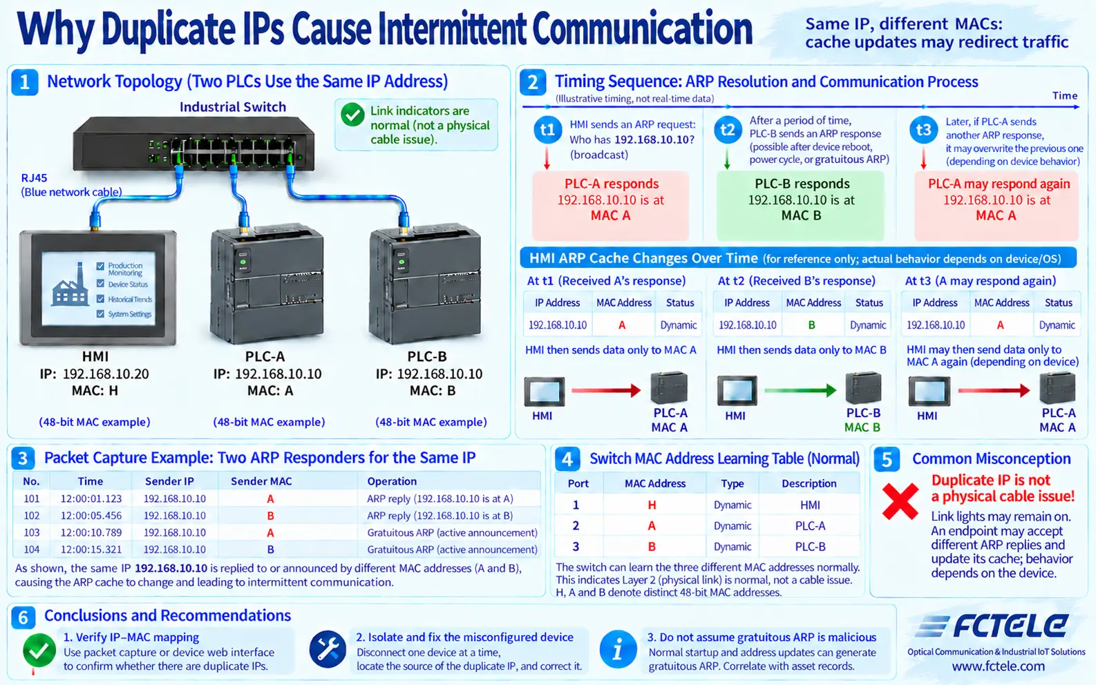
Why duplicate IP addresses can make communication intermittent
If PLC-A and PLC-B both use 192.168.10.10 but have different MAC addresses, both may answer the same request. Which mapping the HMI accepts and whether it changes later depends on arrival order, cache rules and the implementation. A mapping to A sends business frames to A; a later mapping to B may redirect them to B. Symptoms can include intermittent access, communication with the wrong device or repeated connection establishment. Duplicate IPs do not necessarily alternate on a fixed schedule.
The switch may correctly learn A and B on separate ports and both physical link LEDs may remain normal. The fault is a non-unique IP identity, not necessarily an optical loss or a damaged port. Gratuitous ARP or other unsolicited announcements can occur during normal startup or address changes. One announcement alone does not prove an attack; compare repeated evidence of one sender IP associated with multiple MACs against the asset inventory.
Capture ARP and record target IP, reply sender IP, sender MAC and time. Then associate each MAC with a switch port and a physical device. Repeated conflicting mappings call for checks of static addresses, replacement-device settings and maintenance laptops. A single failed ping is insufficient evidence. Isolating equipment or changing addresses must be planned within an approved maintenance window, rather than performed casually on a running production line.
Narrow the fault using observable evidence
First verify IP settings, masks, routes and VLAN membership. Then inspect the initiating endpoint cache and capture a deliberate access attempt. No visible request may mean a cached mapping, a different interface or the wrong capture point. A request without a reply calls for checks of target availability, the same-VLAN forwarding path and target addressing. A stable mapping with no application communication calls for checks of application ports, access controls and the device service.
Before clearing a cache entry, preserve the original mapping and capture evidence. Clear only the authorized endpoint entries concerned and observe resolution again. Clearing a cache may provide a temporary recovery or immediately relearn the wrong device; it is not a permanent fix. Across subnets, verify gateway reachability, routing and the return path. Broadcasting locally to resolve a remote endpoint does not follow normal next-hop selection.
FCTEL's official documentation for its managed industrial switch with 24 Gigabit electrical ports and four Gigabit optical/electrical combo ports lists VLAN, port mirroring, port statistics and MAC filtering/binding functions. VLAN helps establish the broadcast scope; mirroring supports capture; MAC tables and statistics help associate traffic with physical ports. Menu details, firmware and mirroring capability must be checked in the particular device manual. These features do not imply automatic detection or repair of every duplicate-IP fault.
Keep the port topology, address inventory, ARP reply mappings and actual application read/write results as acceptance evidence. Include normal startup, approved equipment replacement and power recovery. Verify that every IP resolves to the intended device. This validates the physical link, address resolution and application service separately, rather than substituting a link LED or one successful ping for industrial communication acceptance.
Technical references: RFC 826: Ethernet address resolution. Related FCTEL resources: Technical Articles and industrial switch product documentation (Chinese).
