


An Ethernet cable plugs into a switch, but a small transformer often separates the cable from the internal circuit. If its two windings have no direct copper connection, how can data cross? And why can a motor starting still disturb an isolated port? Understanding these questions helps separate signal transfer, electrical isolation and interference immunity. This guide uses a typical magnetically isolated copper Ethernet interface as its example, with visible windings and signal paths instead of equations. The generic circuits do not represent the internal construction of a particular FCTEL product.
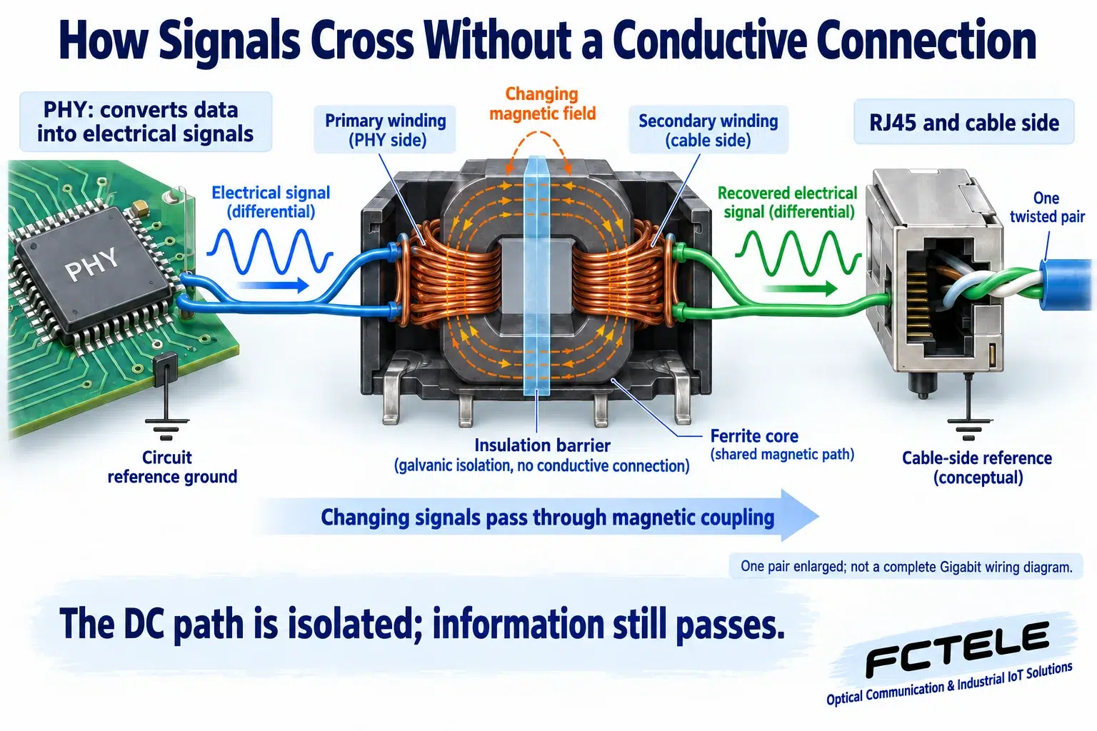
1. The parts inside an Ethernet port
A computer or switch cannot send its internal digital data unchanged down a cable to a distant device. The PHY, or physical-layer transceiver, converts data into electrical signals suitable for the cable and recovers data from incoming signals. RJ45 is the familiar connector. Magnetic components commonly sit between them, either separately on the circuit board or integrated into the connector. Not seeing an exposed transformer block does not prove that isolation is absent.
This transformer serves the communication interface. It is not the large power transformer supplying the entire device. Connections differ with Ethernet speed and circuit architecture, so one drawing cannot describe every port. The illustrations enlarge only one pair. Gigabit copper Ethernet typically uses four pairs with bidirectional transmission on each; the enlarged view must not be mistaken for a complete two-wire Gigabit connection.
2. Information crosses a magnetic path, not a connecting wire
Imagine two separately wound coils. The primary and secondary windings do not share a direct copper connection, but a magnetic core couples them. When current in the primary changes, the magnetic field changes too, inducing a corresponding voltage in the secondary. Information passes through that changing field rather than through electrons moving directly from one winding into the other.
A simple analogy is seeing someone gesture through a glass partition. The partition prevents direct contact but still allows changes to be observed. The analogy explains separation with information transfer only: an Ethernet transformer uses electromagnetic induction, not light, and does not understand packet contents. Signal shape, physical-layer encoding and component bandwidth must suit each other. Arbitrary voltage changes cannot all cross without distortion.
The core makes magnetic coupling more effective; it does not add a connecting wire. When reading a circuit illustration, distinguish conductive connections from arrows representing the magnetic field. Two windings inside one component symbol are not electrically shorted. Similarly, a signal appearing on the other side does not imply that a DC conduction path must exist. This distinction is a useful starting point for understanding the interface.
3. Why blocking a DC path does not block normal data
If the primary is driven into a state that then remains constant, it does not continue producing a changing magnetic field once it has settled. The secondary cannot use that steady condition as continuous DC power transfer. Ethernet uses changing signals suited to its physical layer, and the receiver recovers data from those changes. A DC conductor across the isolation barrier is therefore unnecessary for carrying each bit.
Galvanic isolation separates the direct-current conduction relationship between the cable side and the device circuit, helping with potential differences and some interference problems. Its construction and withstand limits still matter: the presence of a transformer does not make every potential difference safe. Interfaces that deliver power, such as PoE, involve additional power paths and isolation design. This is not a PoE wiring guide and is not a basis for modifying a port.
4. Why shared disturbances can sometimes be rejected
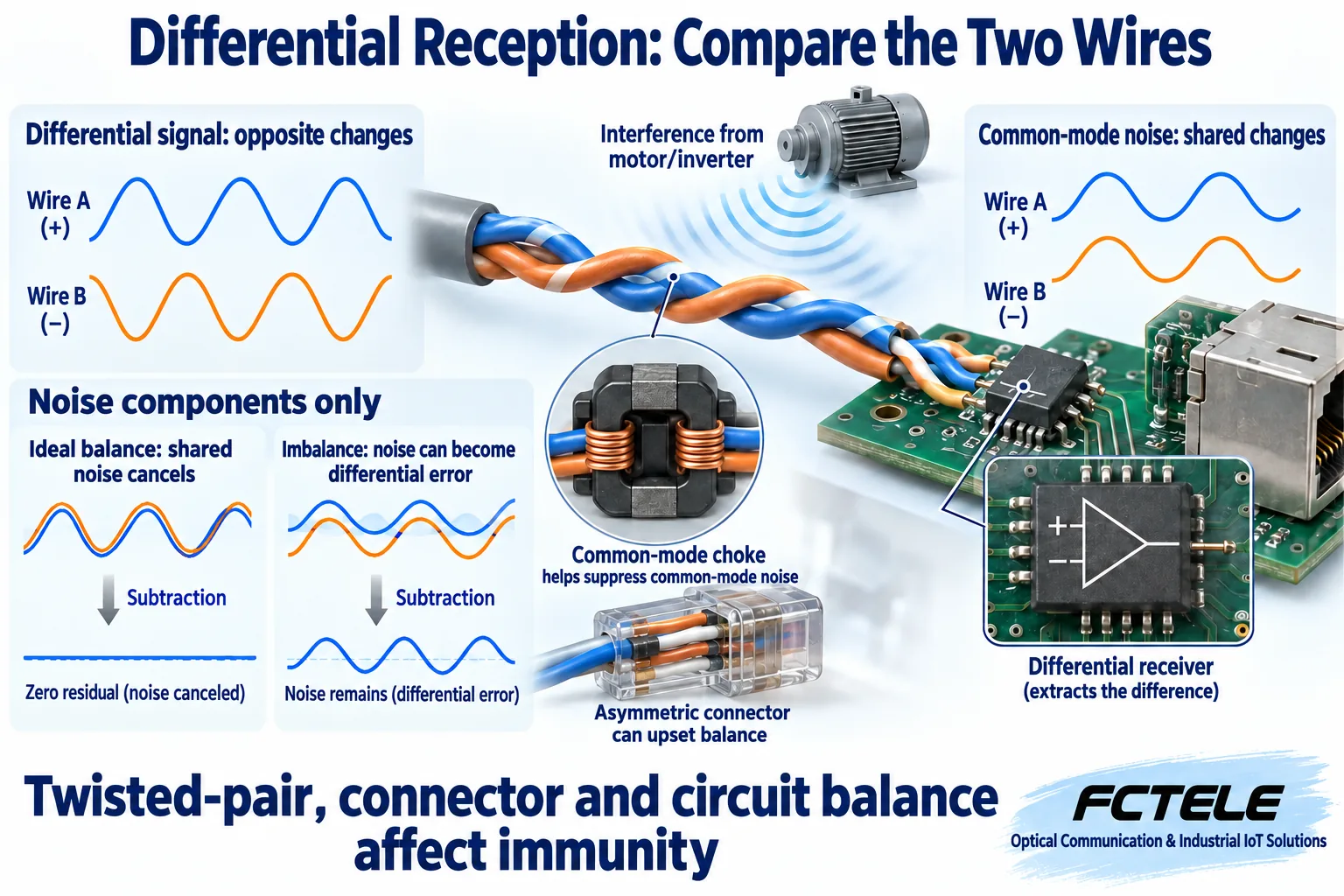
A twisted pair works as a pair, and the receiver mainly observes the difference between its two wires. This is differential reception. The wanted information appears as changes between the wires, while some external disturbances affect both in a similar way. Those shared disturbances are called common-mode interference. In an ideally balanced system, the shared change does not turn into the same effective differential data.
Twisting repeatedly exchanges the wires’ spatial positions, helping them experience similar external effects. A common-mode choke is another familiar magnetic interface component that helps suppress common-mode noise; its main role differs from that of the isolation transformer. Real wires, windings and circuits are imperfect. An asymmetric connector, excessively untwisted pairs, or unbalanced components and layout can turn common-mode interference into differential error visible to the receiver.
Differential reception does not simply ignore every outside influence. A shared disturbance that exceeds the receiver’s allowed operating range can prevent correct operation even if both wires experience similar changes. Practical immunity depends on both balance and the component and equipment limits. Saying that both wires receive the same interference is not a reason to omit protection.
5. Why strong interference can still cross an isolated interface
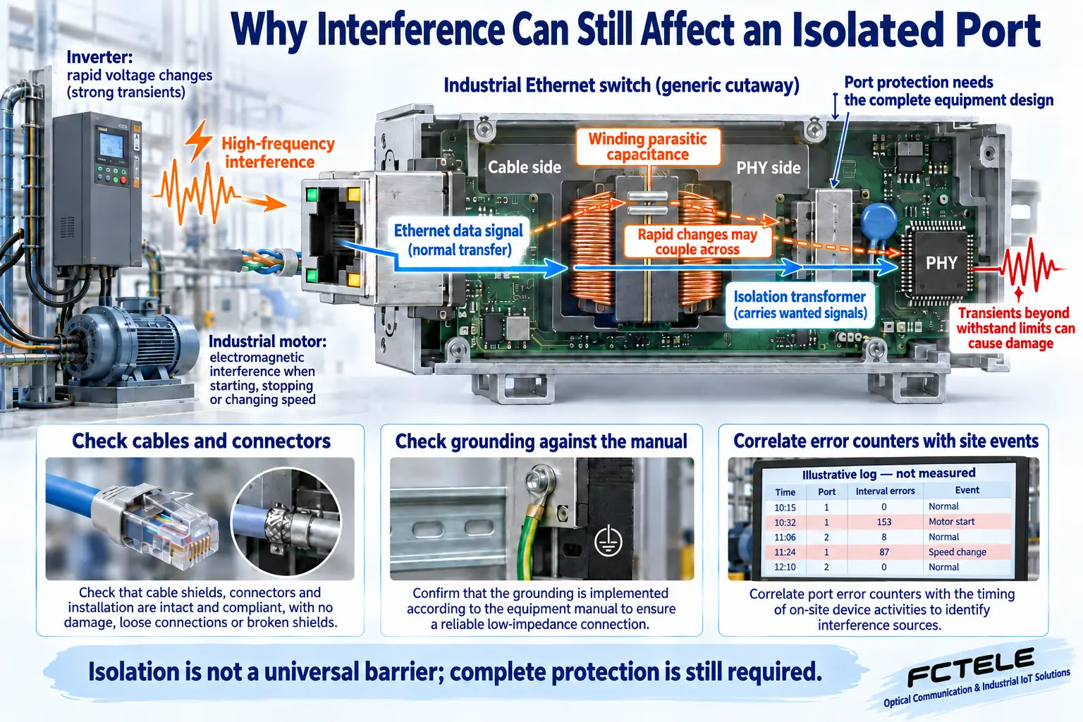
The windings have no direct connecting wire, but they are not completely independent at high frequencies. A small parasitic capacitance exists between the conductors: think of it as a tiny coupling path inherent in the physical construction. Rapid voltage changes can carry interference through that path. Magnetics, interface layout, shielding and protection circuits must work together. One component is not an infinitely strong barrier.
Transients beyond the port and equipment design limits can still cause errors, resets or damage. An isolation transformer is neither a universal lightning protector nor a guarantee that the link never drops. Grounding, shield connections and surge protection must follow the equipment instructions and site design. Do not remove protective connections or bridge the two sides with a wire to hide a symptom. The illustrated coupling path is generic, not a statement about the internal circuit of a particular product.
6. Correlate the symptom with the disturbance
For a link that normally works but occasionally disconnects when an inverter starts, record the time, affected port and application symptom first. Determine whether the link is actually being re-established or whether the link remains up while the application fails. Check the error, discard and connection-event information that the device supports. Changing error counters are clues, not direct proof of a failed transformer. Power, connectors, cabling and software can produce similar symptoms.
Change one factor at a time under controlled conditions, such as substituting a verified cable or changing how communication cables run beside interference sources. Keep before-and-after records. Preserve pair relationships when terminating cables and follow applicable shielding and termination practices. Simply connecting all the colored wires does not prove adequate high-frequency performance. Qualified personnel should handle live-cabinet checks and grounding changes through the established maintenance procedure.
Distinguish the outer shield from the signal pairs as well. Shield connections have their own role; they are not transformer windings and should not be disconnected merely to pursue complete non-conduction. Record which connection changed and under what conditions the result improved. A symptom that disappears briefly without testing the original triggering condition does not establish the cause.
7. Verify the equipment, not just the component name
FCTEL managed industrial switch documentation helps identify interfaces, deployment arrangements and available management functions. The actual model, firmware and manual remain the basis for acceptance. Copper ports, optical ports and an industrial enclosure do not reveal a particular port’s isolation rating, immunity class or protection components. Copper-interface magnetics and optical-fiber transmission also use different mechanisms; this explanation cannot simply be transferred to an optical port.
After recovery, observe link stability and test the real application under the conditions that previously triggered the fault. Retain records of cabling, layout, power and port events so the results can be compared. Remember the division of work: changing magnetic fields carry signals across transformer windings; differential structures and common-mode components help handle interference; equipment-level protection establishes the practical limits. Understanding these roles is more useful than assuming that the word isolation means the problem is already solved.
Technical references: Analog Devices: Ethernet isolation and coupling; Analog Devices: interface layout and isolation boundaries; Analog Devices: understanding common-mode signals; Analog Devices: parasitic coupling across magnetics; TI: Ethernet PHY and magnetics reference design. Related resources: Technical Articles and FCTEL managed industrial switch documentation (Chinese). Original AI-assisted illustrations show generic principles, not product internals or measurements.
