


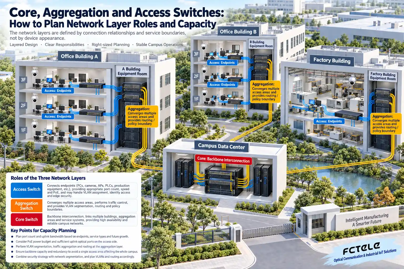
Access, aggregation and core are the roles switches play in a network, not fixed tiers divided by chassis size. The access layer connects terminals, the aggregation layer brings together multiple access areas and serves as a policy or routing boundary, and the core layer handles backbone interconnection. A small network can merge aggregation and core, but it still needs to clearly define capacity, fault scope and management responsibility.
From one computer to an entire campus, responsibilities change level by level
Computers, cameras, wireless APs or PLCs first connect to access switches. The access side needs port counts, speeds and power supply capability suited to the terminals, and may also handle VLAN assignment, identity access and edge security. When purchasing access equipment, you cannot just count network ports; you should also confirm PoE power, the number of optical uplinks and the required management features.
A building has multiple floors, and a factory has multiple workshops. These access devices usually need to be brought together at a building or area aggregation node. Aggregation is not just about gathering cables; it also needs to handle traffic from multiple sources and the impact of failures. A project can set routing and access boundaries between different networks here, but the exact location depends on the design. Not all aggregation devices must use the same configuration.
The core connects multiple buildings, aggregation areas and service resources to each other. It should focus on ensuring backbone capacity and high availability, and avoid a change in one access area expanding into a campus-wide failure. The core also does not have to be a large chassis: when scale, ports and reliability requirements are suitable, fixed-port devices can also take on the backbone role.
Three network layers are not the same as OSI Layer 3
“Three-tier architecture” refers to the three deployment layers of access, aggregation and core; “Layer 3 switch” refers to having network-layer forwarding capability. The two are not the same concept. Access devices can also have Layer 3 capability, and whether a core device can perform the required routing depends on specific software features, licensing and performance. It should not be judged by name alone.
“Ordinary switch” is also a vague term. It may be a small unmanaged device, or it may be a fully featured fixed-port managed switch. When comparing, you should convert it into verifiable parameters, such as VLAN, routing, link aggregation, redundancy, access control and management capabilities. Checking models after clarifying requirements is more reliable than using ordinary or advanced labels.
How do you calculate the uplink bottleneck? First look at business that happens at the same time
A device having many gigabit ports does not mean the uplink will always need the sum of all ports at rated speed. The key is which terminals transmit at the same time, where the data goes, how long the peak lasts, and how much latency and packet loss the business allows. Cameras with continuous streams, file backups and control communications have different load characteristics, and the same utilization assumption cannot be applied to every project.
If multiple access switches send data to the same recording server, both the aggregation uplink and the server port may become bottlenecks. A device’s rated switching capacity is also not the actual available bandwidth of a particular egress. You should also pay attention to forwarding capability, buffering, port speed, performance after features are enabled, and small-packet load, and ultimately verify with project business or representative load.
Merging layers is fine, but do not merge away risk judgment
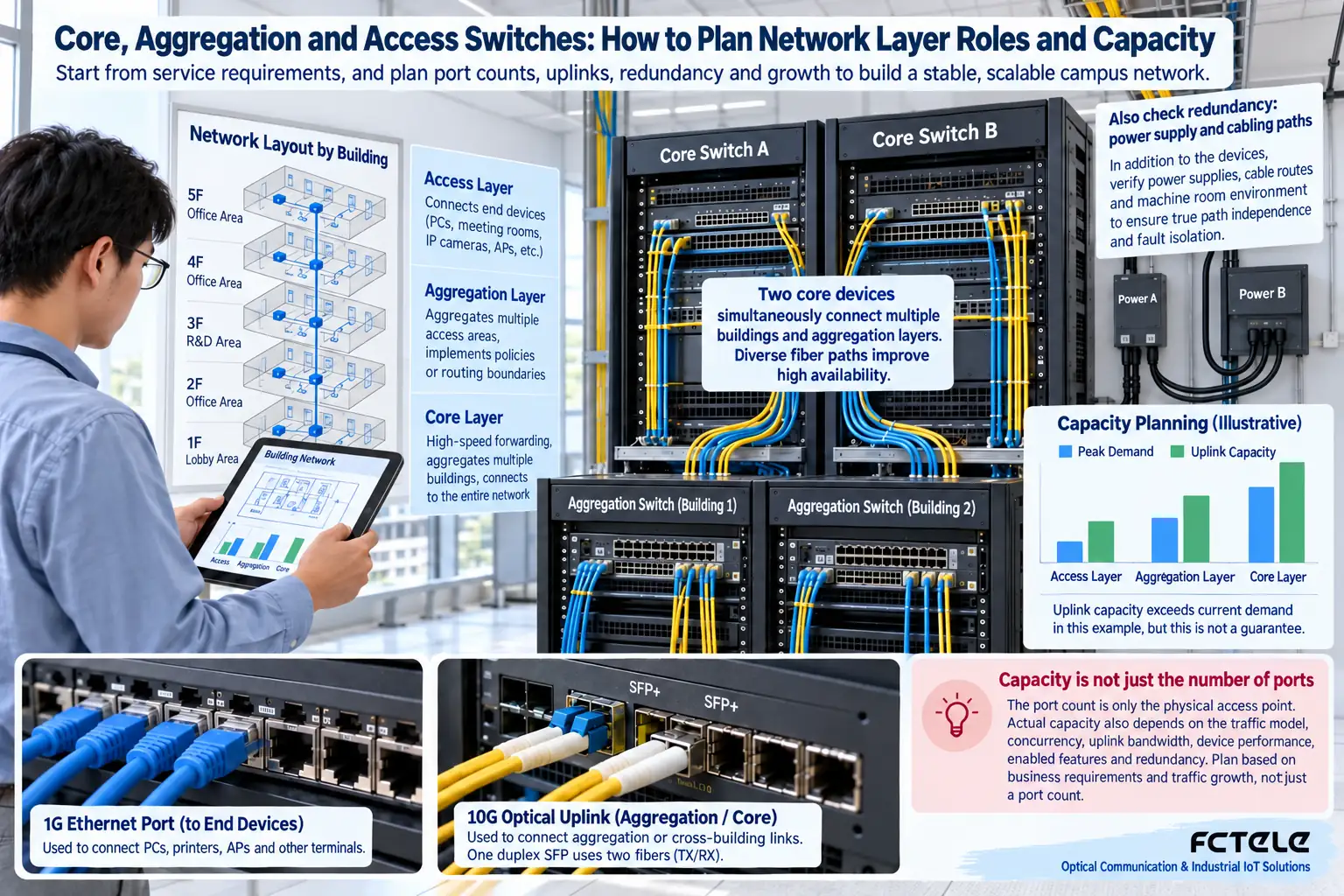
A single building or small campus can use a two-tier design that merges aggregation and core, reducing equipment and maintenance complexity. In this case, the merged node takes on multiple responsibilities at the same time, so you should check whether a failure will affect all terminals, whether there is a usable backup, and whether maintenance and upgrades can be scheduled. Fewer devices does not automatically mean less risk.
After the campus expands, adding an independent core layer can let multiple aggregation areas interconnect through a unified backbone and reduce the complexity of connection relationships. But adding a layer does not necessarily improve reliability. If power, optical cables and management configuration still share the same weak point, the new devices may only add more things to maintain.
Draw redundancy onto the real path
If two optical fibers are in the same duct that is easily dug up, they do not have complete path independence. If two devices use the same power branch, they may also lose power at the same time. Redundancy planning should check devices, interfaces, power, cable paths and upper-layer services item by item, and clearly define which kind of failure is being protected against, rather than assuming everything is safe just because two icons are drawn.
Dual uplinks also need suitable forwarding and convergence mechanisms, such as spanning tree, link aggregation or routing protocols. Their functions and deployment conditions differ, and dual links cannot be casually connected in parallel and allowed to form an uncontrolled loop in the network. For multi-vendor devices, verify specific feature and configuration interoperability, not just that feature names are the same.
Before expansion, you should also collect the actual traffic and abnormal periods of existing uplinks, and clarify where the business of new terminals will go. Adding a large number of cameras to a certain floor may first affect the path from aggregation to the recording server, not all core ports. Planning expansion based on real data can avoid replacing only one larger chassis without improving the egress bottleneck.
Write acceptance tables by responsibility, judge results by business
On the access side, verify terminal connections, VLAN, PoE and management; on the aggregation side, verify simultaneous traffic, policy boundaries and uplink failures; on the core side, verify backbone capacity, backup paths and service reachability. For critical business, record normal load and failure recovery results, and distinguish port recovery, network recovery and application recovery. After delivery, keep topology, port labels and configuration backups to help judge the scope of impact during expansion.
Architecture reference:Cisco Campus Network Design Guide. Product selection still needs to be based on this project’s requirements and model documentation.
Translated from the Chinese technical article. Source first published: 2019-09-25. Source last revised: 2026-10-13T23:18:15+08:00. Read the Chinese source
