


Field or portable fiber optic transmission devices emphasize temporary deployment, carrying and transport, reliable connections, and environmental adaptability, using fiber to transmit video, Ethernet, telephone, or other specified services between on-site stations. The words “field” or “industrial” in the name cannot prove that the equipment reaches a certain military, waterproof, or safety rating; actual capability must be confirmed by model documentation, test conditions, and project acceptance.
What extra constraints does field use have compared with indoor use?
A fixed equipment room has stable power, a patch panel, and a controlled environment; a temporary site may not have these conditions. Equipment must endure transport, frequent connections, dust, moisture, temperature changes, and limited power. Reliable deployment is not about putting an ordinary fiber optic transmission device into a rugged box; it means designing the equipment, interfaces, cables, power, and operating procedures as a whole.
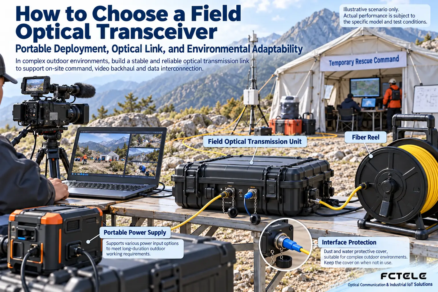
Emergency communication, outdoor activities, temporary monitoring, and long-distance construction sites may all require portable optical transmission. First determine the services and the relationship between sites: what signals to transmit, how many channels, which direction, whether interruption is acceptable, and who is responsible for power. Without these conditions, comparing only chassis weight or advertised distance cannot select a suitable solution.
Multi-service interfaces: not all signals can be mixed at will
Video, Ethernet, serial, telephone, and switch contacts may be handled by different interface boards or designated channels. Not every RJ45 is necessarily Ethernet, and not every terminal is necessarily power. Before deployment, check the electrical standard, pins, rate, and direction of each interface, and use the corresponding wiring diagram. Telephone interfaces also require identifying the power-feed and wiring roles, and video interfaces require checking the format.
If a product supports multiplexing multiple services, confirm the total capacity and channel limits when the combination is enabled; do not add the individual maximum specifications of each interface and assume all can be achieved simultaneously. Ethernet services also require considering addresses, VLANs, and upper-layer services, while dedicated serial ports require checking communication parameters. Acceptance should cover the service combinations planned to work simultaneously.
How far a fiber cable reel can lay out is not equal to how far the link can certainly reach
The reel specification indicates how much cable can be laid out on site; it does not mean the optical power budget is sufficient. Actual loss also includes the fiber core, connectors, splices, and intermediate components; the receiver must operate between sensitivity and overload upper limit, with appropriate margin. A long-distance module connected to a short patch cord also requires confirming received power; stronger is not always better.
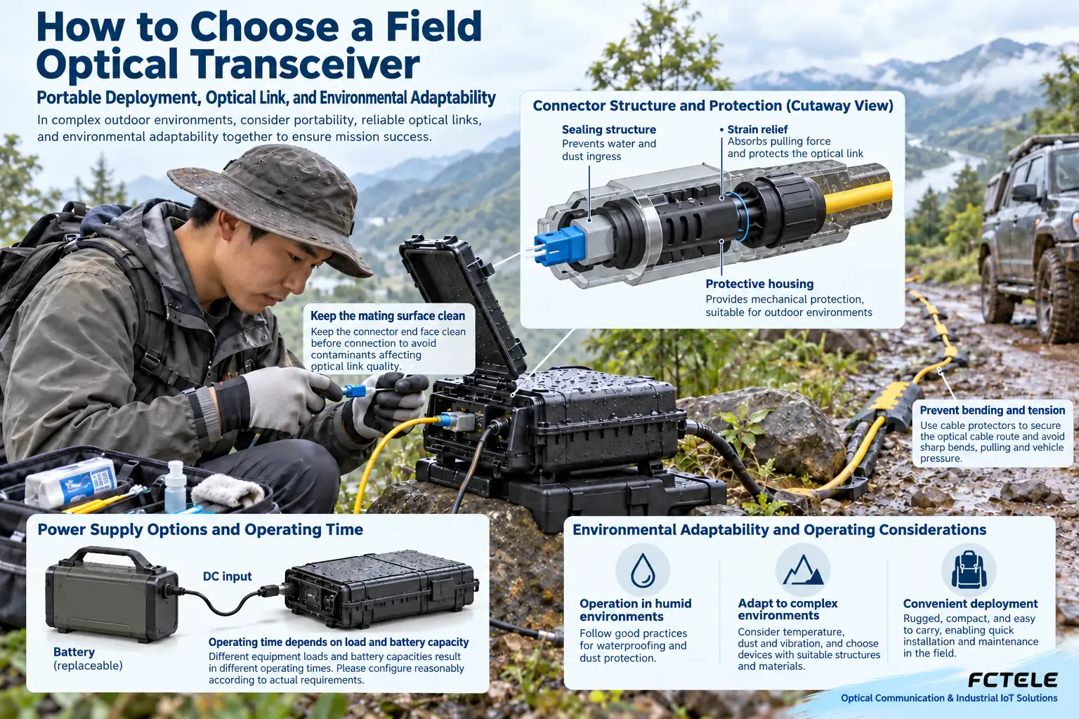
When laying cable, choose a jacket and mechanical protection suitable for the site, avoiding vehicle crushing, sharp-edge cutting, too-small bend radius, and directly pulling connectors. Crossing passages requires protection and marking according to on-site rules. When coiling cable, check for damage and contamination, and coil according to cable requirements; the next rapid deployment depends on correct storage the previous time.
Waterproof, wide temperature, and vibration resistance all require usage conditions
Protection ratings should specify the test standard, whether interfaces are connected or covered, the chassis state, and the allowed environment. Protection capability in the closed state cannot be directly applied to live operation with interfaces open. Connecting and maintaining in wet environments must follow product and on-site electrical safety regulations; one cannot infer from a waterproof label that connections can be made in rain.
Wide temperature range also requires checking whether the equipment and the optical modules, power supply, and cables used meet the requirements together. Transport vibration, operating vibration, and shock tests may have different conditions, and reports must correspond to the specific model. When documentation is absent, mark it as “to be verified”; do not invent certifications, temperature tolerances, or military-grade promises for the product.
Portable power: first consider energy, not just voltage matching
Input voltage, polarity, and connector should match the nameplate, and consider startup, full-load services, and power consumption of other terminals. If battery capacity is expressed in ampere-hours, it must be converted to energy together with voltage, then consider conversion loss, usable capacity, and actual load to estimate runtime. Nominal capacity cannot be directly treated as guaranteed battery life.
Backup power and charging solutions should cover the deployment duration, and record whether switching causes restart and whether alarms are visible. The fiber itself does not carry electricity, but that does not mean the entire system does not need grounding or surge protection; metal armor, power, and copper interfaces should still be handled according to on-site design.
Fiber transmission also does not automatically equal service encryption or access security. If the site needs to protect data, authentication, access control, and appropriate encryption mechanisms should also be designed according to threats and management requirements; management ports also need protection. Transport case locks and the physical properties of fiber cannot replace network security configuration. During drills, confirm that terminals, management accounts, and configuration backups are maintained by designated personnel, avoiding unclosed access entry points left after temporary deployment ends.
Complete a repeatable drill before departure
Build a short link with actual equipment, cables, and power, and check port numbering and each service. Then deploy according to the planned scenario, recording reception status, service stability, power, and recovery results. When rapid deployment is needed, focus on whether two or more people can complete connections according to the same labeling, rather than only testing whether a technician can connect it themselves.
The delivery package should include a port table, cleaning and protection tools, applicable spare parts, power instructions, and normal status records. For on-site abnormalities, first distinguish power, optical path, interface parameters, and service configuration, and retain test conditions and results. The images in this article are schematic illustrations of principles and scenarios, not proof of rating for specific equipment; when specialized procurement standards are involved, the corresponding documents and test evidence must be verified separately.
Translated from the Chinese technical article. Source first published: 2020-03-12. Source last revised: 2026-10-13T23:18:15+08:00. Read the Chinese source
