


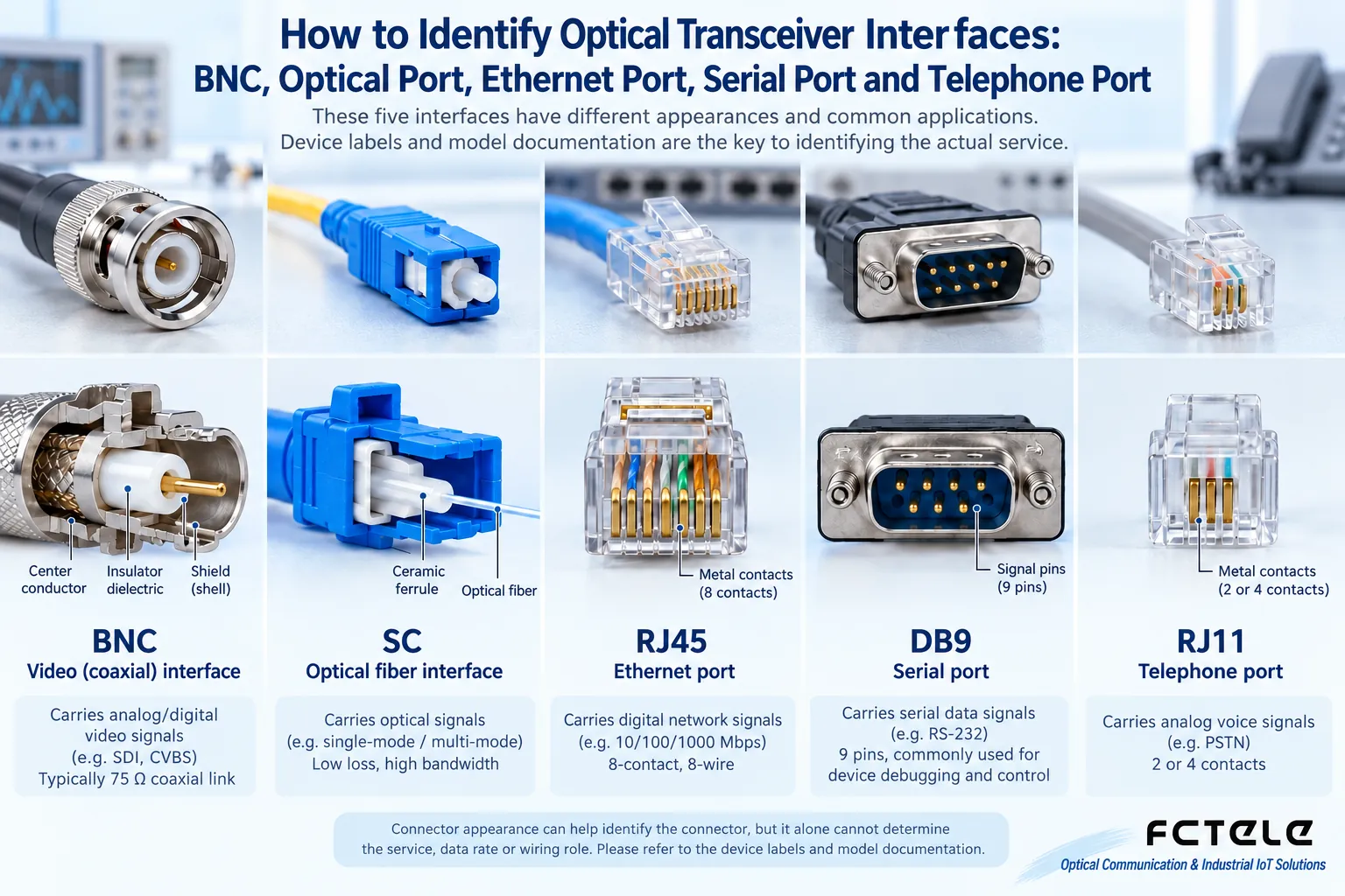
Common interfaces on fiber optic transmission devices include BNC, optical fiber interfaces, RJ45, serial ports and telephone ports. The shape can only help you recognize the connector; it cannot by itself determine the service, speed or wiring role: the same BNC may carry different video or E1 signals, and the same telephone port may be FXS or FXO. You must check both the device markings and the manual.
BNC: first identify the signal, then match the coaxial cable
BNC is a bayonet-style coaxial connector, not an abbreviation for “basic network card.” It can appear in analog video, SDI and other professional interfaces. Video systems often use 75Ω coaxial links, but you cannot therefore assume that all BNC interfaces use the same impedance or format, and you certainly cannot freely interconnect a video input with other service interfaces.
Even if a CVBS camera and an SDI fiber optic transmission device have the same plug, their services may be incompatible. You should check the input/output direction, signal format, allowed distance and cable requirements. BNC connectors need to be locked securely; impedance mismatch and poor contact may introduce reflections or bit errors. By itself, BNC does not automatically convert different signals into a compatible format.
Optical port: SC and LC are not speed grades
SC, LC, FC and ST describe different connector structures. SC commonly has a push-pull square housing, LC is smaller, FC is screw-fixed, and ST is commonly bayonet-fixed. They do not mean that one type can only do 1 Gbps and another can only do 2 Gbps. The speed of an optical port is determined by the optical module, transceiver and system specifications, and cannot be inferred from the connector name.
You also need to check single-mode or multimode, wavelength, single-fiber or dual-fiber, transmit/receive direction, and end-face polishing method. UPC and APC should not be mixed at will. An optical connection aligns the fiber core through a precision ferrule; it does not transmit electrical signals through copper contacts. Being able to connect the plug does not mean the optical interfaces are compatible. During maintenance, check and clean the end face, and do not look directly into the optical port.
RJ45: usually Ethernet, but check the label
The 8-position modular interface commonly called RJ45 is widely used for Ethernet, and network cables are made according to specifications such as T568A or T568B. Fixed speed and auto-negotiation capability still need to be checked in the device documentation; not all devices support automatic conversion between 100 Mbps and 1 Gbps. The electrical port of a transceiver connects to the local network, and the optical port extends the remote link. This does not mean it can connect to a PON broadband authentication network.
Some Console management interfaces also use a similar shape, but they carry serial management signals, and you cannot plug them into an ordinary Ethernet port and expect communication. PoE capability, data ports and management ports should all be confirmed based on panel labels and the manual. Modern devices that support Auto MDI-X can often adapt to the wiring direction, and T568A should not be equated with a dedicated “crossover cable” standard.
Serial port: look at the electrical standard and the plug separately
RS-232, RS-422 and RS-485 are electrical interface specifications, not names exclusive to a particular plug. DB9, DB25 or terminal blocks may all carry serial ports, but the pin definitions are not necessarily the same. RS-232 usually uses a single-ended signal relative to a reference ground, while RS-485 uses differential transmission, and they cannot be interconnected unconditionally.
When connecting a controller, you also need to check the DTE/DCE role, TX/RX, reference ground, and baud rate, data bits, parity and stop bits. The A/B naming of RS-485 may differ, so verify according to the signal definition. You should not infer a fixed maximum speed or maximum distance from the DB9 shape; actual capability depends on the transceiver circuit and cable conditions.
Telephone port: FXS and FXO must correspond
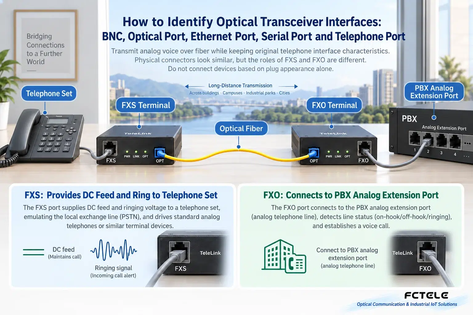
The common modular telephone connector is smaller than a network port. The actual number of contacts used should be based on the interface specification; it is not “six pairs of copper wires.” A telephone is usually connected to an FXS port, which provides the corresponding power feeding, ringing and signal. FXO usually connects to the analog extension port of a PBX or the corresponding telephone line. If the roles of the devices at both ends are chosen incorrectly, it may be impossible to go off-hook, dial or ring.
When deploying a telephone fiber optic transmission device, first draw the complete path of the telephone, FXS device, optical fiber, FXO device and PBX. Then check service compatibility such as dialing, ringing and caller ID display. Do not accept it based only on the presence of a dial tone. The ultimate goal of interface identification is to determine “what is transmitted, where it connects, and how to verify it,” not to memorize a list of shape names.
Translated from the Chinese technical article. Source first published: 2020-04-28. Source last revised: 2026-10-13T23:18:15+08:00. Read the Chinese source
