


100G optical communication testing cannot just confirm that a module can be inserted or that a link light is on. It is necessary to distinguish module interfaces, optical transmission methods, optical power, bit errors, and actual Ethernet performance, and to verify according to specific standards and equipment conditions. 100G is no longer a concept described only as “coming soon”; the engineering focus is how to prove that a link meets requirements.
100G describes a rate, not a single structure
For the same 100G, optical modules may use different optical standards, fiber types, wavelengths, and parallel methods. Chassis slots and module form factors are also only partial compatibility conditions. Equipment support for modules, configuration, and firmware must be checked; one cannot judge based only on the letters QSFP.
Some solutions use multiple electrical lanes, and the optical side may be parallel fiber cores or may combine multiple wavelengths. The number of electrical lanes does not equal the number of field cable cores. Saying all 100G uses a fixed four fibers will mislead cabling and testing.
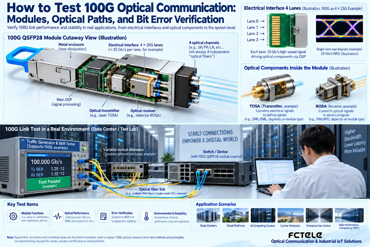
Read the interface standard first, then choose the test method
For example, SR4 and LR4 have different fiber types, optical interfaces, and optical lane arrangements, and the test method must match the corresponding standard. For specific differences, refer to Cisco module documentation, but model numbers and values in the documentation cannot be directly applied to other products.
At the same time, confirm the switch port mode, required error correction capability, and module configuration. Being able to establish a link does not mean all parameters meet project requirements, and necessary functions should not be turned off to hide compatibility issues. Module diagnostic data also requires understanding the measurement range and accuracy.
Normal optical power does not necessarily mean bit errors pass
Optical power measurement reflects the energy level and needs to be compared with the receive range; bit error testing focuses on whether the recovered data is correct. Signal quality, noise, reflection, and receiver performance can all affect bit errors. Measuring only one average power value cannot replace complete signal quality verification.
Eye diagrams or related signal quality observations can be used to analyze modulation and waveforms, but appropriate instruments, bandwidth, and test conditions should be used. Interpretations for different modulation methods cannot be mixed, and a pretty screenshot should not be treated as an unconditional certificate of passing.
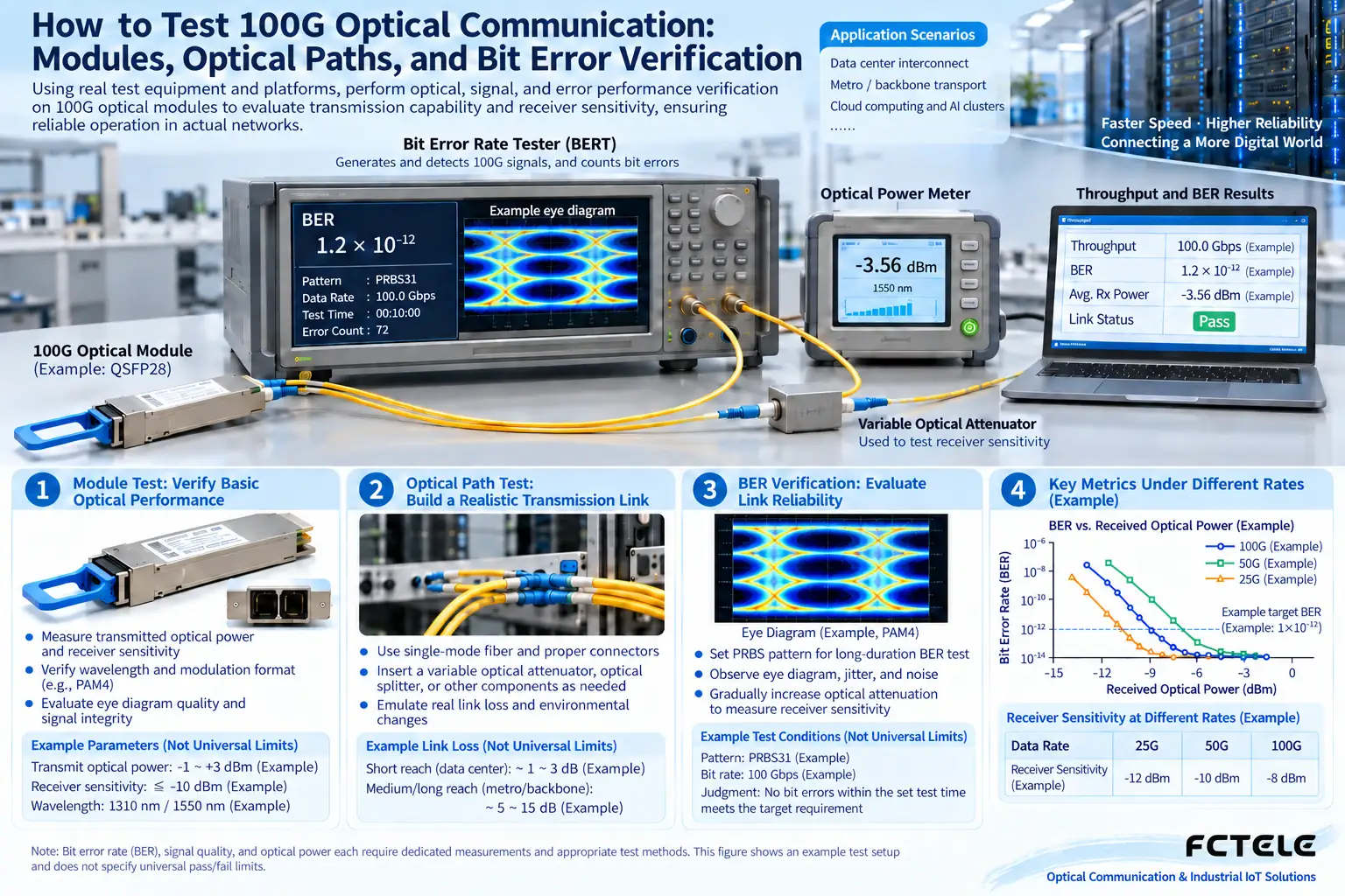
How to distinguish link rate from application throughput
The nominal rate of a 100G port does not mean that application file copying will necessarily reach the same value. Packet overhead, CPU, storage, software, and network topology can all limit the application. When testing switching capability, use tools that can reach the required load, and state the frame length and traffic conditions.
Throughput, latency, jitter, and packet loss each express different performance aspects. Long-term stability also requires observing temperature, error counters, and runtime. A small amount of data passing once cannot prove that full load or continuous business meets requirements.
Field optical cables also need acceptance
Check end faces, polarity, connections, and line loss, and determine the test path according to the suitable optical interface. Parallel connectors and multi-wavelength solutions each have points to note; do not infer supported standards from color or core count. Recheck after cleaning, and do not look directly into optical ports.
Short-link back-to-back testing can help distinguish module problems from field line problems, then gradually add patch cords and optical cables. The test report should record modules, versions, fiber types, wavelengths, tools, and configurations so that results can be repeated, rather than leaving only the sentence “100G succeeded.”
How to understand the opportunities brought by test requirements
High-speed systems impose finer requirements on compatibility, measurement, and maintenance, but without a clear statistical source, market size or commercial returns should not be fabricated based on this. For engineering, the value comes from accurately locating faults, reducing rework, and establishing credible acceptance documentation.
When equipment procurement is needed, check the actual rates and supported ranges in the Product Center. Do not assume that all Feichang Technology products support 100G just because the article discusses 100G. Clarifying technical boundaries is more helpful for correct selection than expanding the scope of publicity.
The illustrations are schematic diagrams of scientific principles and application scenarios; the interfaces, structures, and measurement values in them do not represent specific product parameters. Actual specifications must be based on model documentation and on-site measurements.
Translated from the Chinese technical article. Source first published: 2019-06-28. Source last revised: 2026-10-13T23:07:12+08:00. Read the Chinese source
