


A PoE fiber optic transceiver converts fiber Ethernet service to copper cable, and a compatible PoE port supplies power to devices such as cameras and APs. Ordinary fiber only carries data, not PoE power; the remote transceiver still needs a suitable power supply. When using it, you must confirm optical port interoperability, data rate, PoE standard, and power budget at the same time. You cannot treat simply connecting the fiber as completing the installation.
Draw the data path and the power path separately
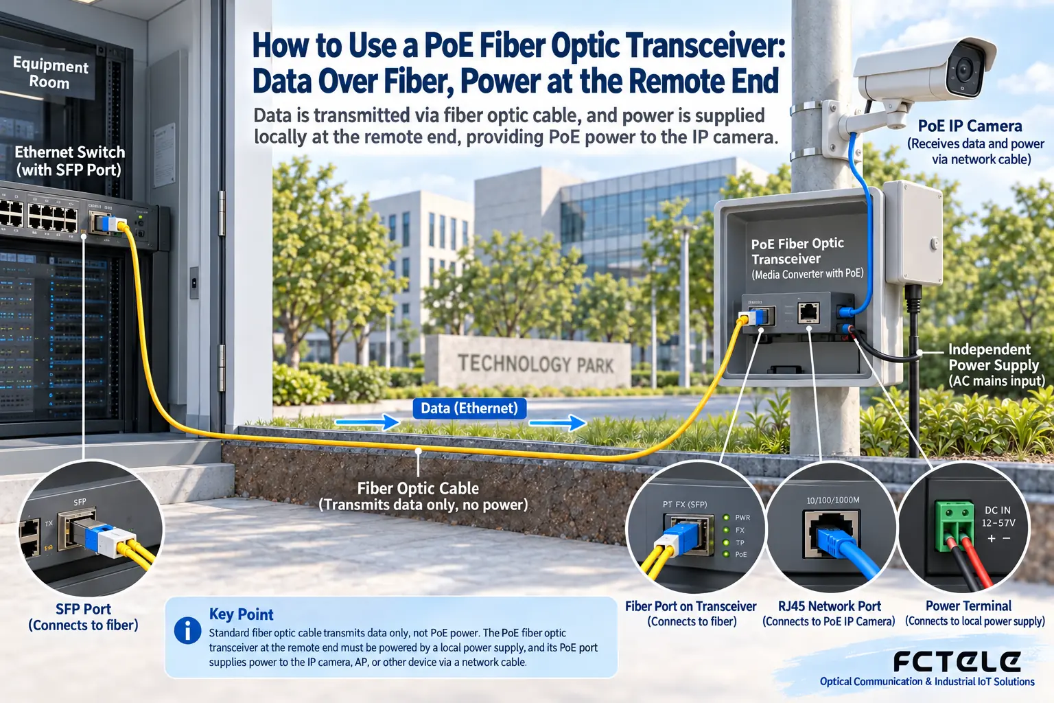
One common solution is: the optical port of the central switch connects through fiber to the optical port of the remote PoE transceiver, and the transceiver’s RJ45 copper port then connects to the PoE camera. The camera’s power comes from the remote transceiver’s local power supply, not from the central equipment room sent along the fiber. If the center has no optical port, matching media conversion equipment may also be needed.
Some products are PoE powered devices, PoE splitters, or have multiple power modes. Their names are similar, but their roles are different. When purchasing, you should confirm whether it is a PSE that supplies power to other devices, or a PD that receives power from the network cable, and whether optical-to-electrical conversion and power supply can both meet the target requirements.
Optical port pairing must satisfy more than just the connector
Check the Ethernet standard, optical rate, single-mode or multimode, single-fiber or dual-fiber, and wavelength conditions. Dual-fiber usually uses TX to RX, while single-fiber BiDi requires complementary transmit and receive wavelengths; two devices with the same wavelength role cannot be treated as an arbitrary pair. The fact that an SFP can be inserted does not mean the device supports that module’s rate or coding.
Calculate the link according to the actual optical cable, connectors, and splice loss, and compare the receive range and engineering margin. The nominal distance is only a selection clue; it neither guarantees operation with contaminated end faces nor rules out excessive power on a short link. Use dBm when measuring received optical power and dB for loss, and avoid confusing the units.
If the device powers off after startup, first calculate the complete power account
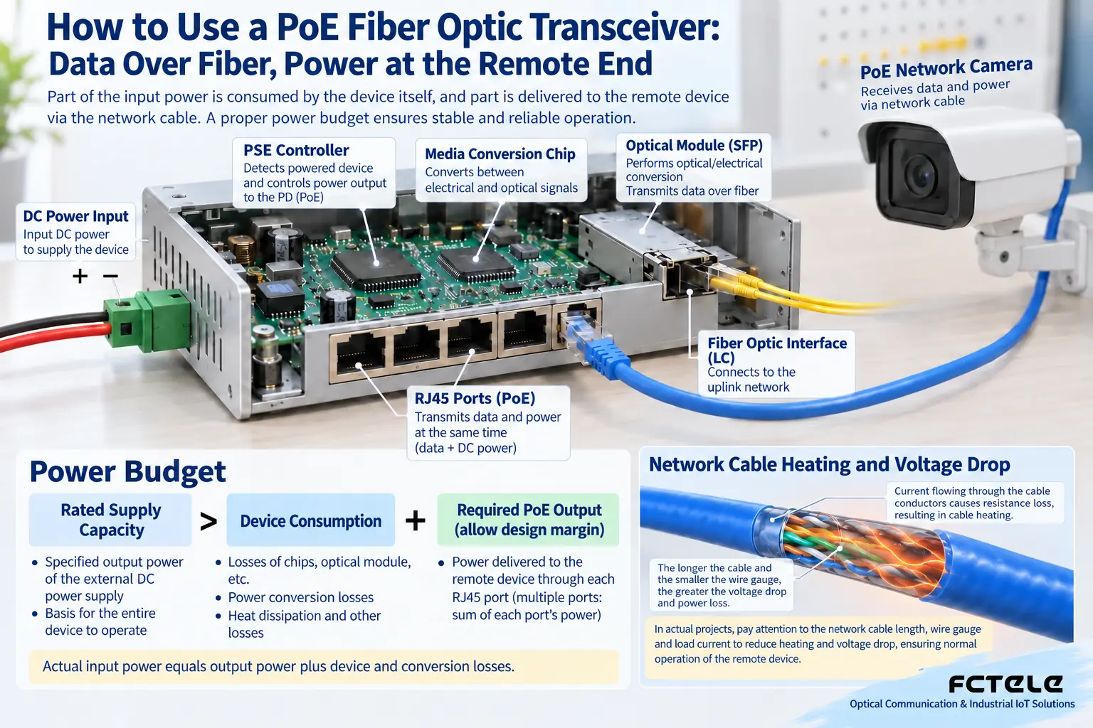
PoE output capability is constrained by the standard type, per-port limit, overall device budget, and input power capability. A camera may consume more when turning on fill light, heating, or pan-tilt movement at night than in standby, and AP load may also change. There is also copper cable loss between the power sourcing equipment’s rated output and the powered device’s available power.
The input power supply also needs to cover the transceiver’s own consumption. You cannot just see the total wattage of the power supply and assume that all of it can be delivered to the camera; you also cannot judge whether full-load operation is stable by using the no-load voltage. Select the power supply according to the device’s allowed input voltage, polarity, peak demand, and operating environment, then verify operation under full load.
A field installation sequence
First verify compatibility on a short-distance test bench, and confirm that the optical link and target terminal can operate normally. After fixing the equipment on site, complete power and grounding as required, protect and clean the end faces, and then connect the fiber and copper cable. The copper cable category, termination quality, and length should all meet the corresponding Ethernet and PoE conditions.
After power-on, first check the power supply status and optical link, then check the electrical port negotiation rate and PD power supply status, and finally verify recording, wireless, or the actual service. Indicator light names and meanings should be explained according to the model; you cannot write the PWR, FX, and PoE light states of one product as a universal judgment table.
Three phenomena correspond to different troubleshooting directions
When the optical port does not establish a link, check the module, wavelength, rate, direction, and optical path; when the optical port is normal but the camera does not power on, check the PoE mode, detection, power, power supply, and copper cable; when the camera powers on but has no service, then check the address, VLAN, network path, and platform configuration. Change only one condition at a time and keep a known-good baseline.
If it repeatedly restarts, record the time of occurrence, load actions, and power supply status, paying special attention to nighttime or low-temperature high-load conditions. Do not use passive power supply mode to forcibly bypass compatibility problems, and do not connect an unknown voltage directly to the terminal. Electrical rectification must follow product and site safety requirements.
Distance extension cannot hide on-site environmental risks
Fiber is beneficial for spanning distance and reducing conductive paths, but the remote power supply, camera network cable, and enclosure still need protection. Outdoor installation should be paired with a suitable box, temperature range, waterproofing, and lightning protection grounding solution; a metal enclosure does not automatically prove that it can be directly exposed to rain outdoors. Do not understand fiber immunity to interference as meaning the entire system needs no protection.
Acceptance should include actual peak load, continuous service, power recovery, and maintenance records. Label the optical ports at both ends, power specifications, camera ports, and measured optical power to make future fault location easier. If multiple terminals are aggregated, you need to reconsider switching capability, uplink capacity, and total power budget; you cannot infinitely split one single-port transceiver.
Reference:Cisco: PoE detection and power management mechanisms.
Translated from the Chinese technical article. Source first published: 2019-12-17. Source last revised: 2026-10-13T23:18:15+08:00. Read the Chinese source
