


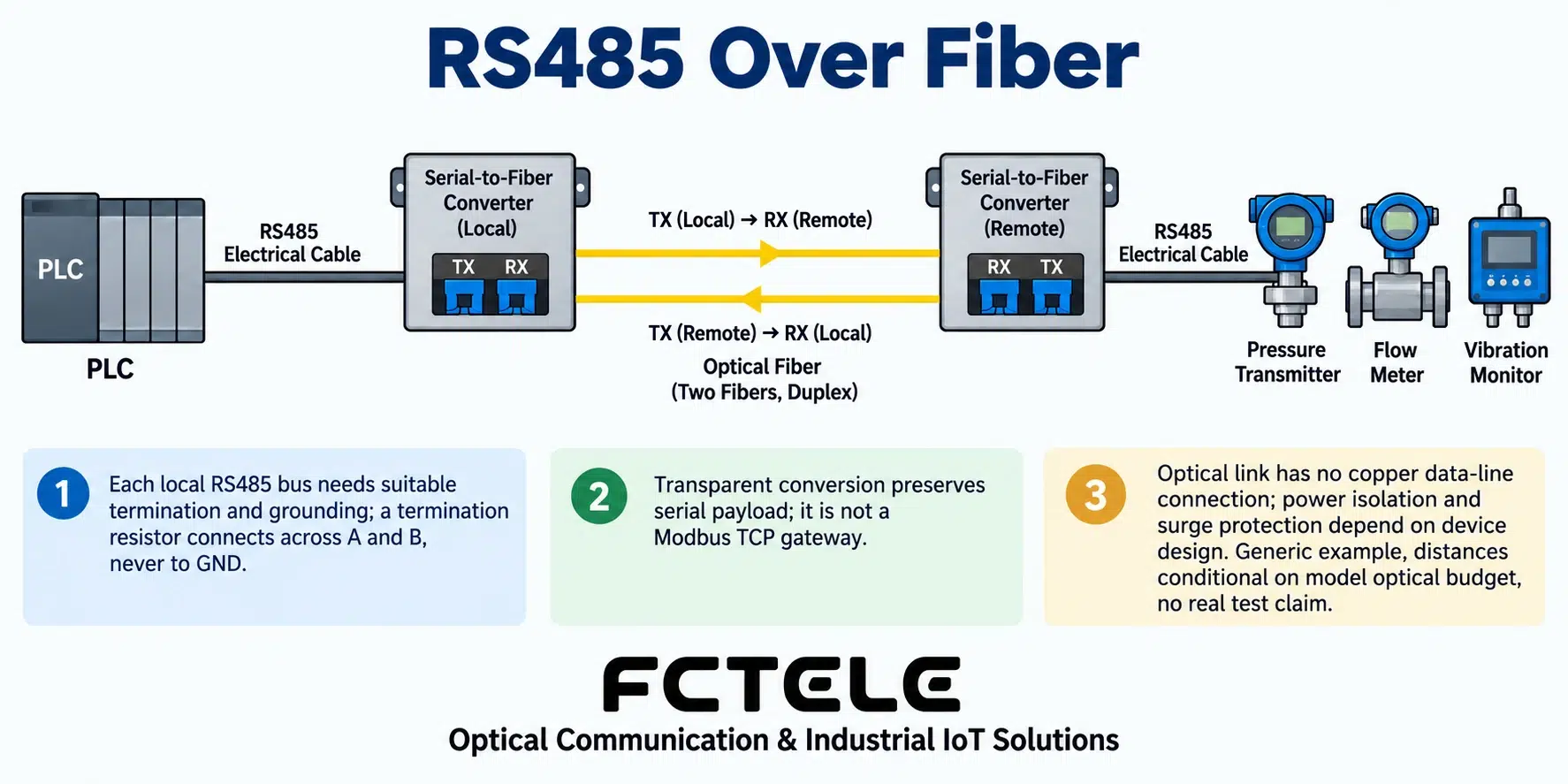
RS485-to-fiber devices carry the data of an RS485 electrical segment over fiber to another RS485 line, making them suitable for serial connections that span long distances and face more complex electromagnetic environments. Transparent models usually preserve the serial data and will not automatically turn Modbus RTU into Modbus TCP. The key points in selection are the serial format, half/full duplex, direction control, optical port pairing, and the response time requirements of the application.
Two electrical segments, connected by an optical link
For example, a PLC in the control room polls instruments in a remote pump house; a short local RS485 line connects the converter, the fiber crosses the campus, and the remote converter then connects to the instrument bus. In this way the long-distance part is carried by the optical medium, and the same copper line does not have to be pulled to the remote end. The fiber segment does not form a copper conductor connection, which helps separate the electrical path of the data line between the two areas.
However, whether the complete unit has an isolated power supply, port isolation, and what kind of surge protection it has depends on the specific structure and testing. Fiber cannot eliminate risks on the device power side, nor does it automatically protect the short copper line at the remote end from lightning strikes or wiring errors.
Transparent conversion is not protocol translation
Transparent devices usually restore the received serial data as the corresponding electrical signal at the other end. The master and slave still use the original addresses, function codes, and data interpretation methods; the converter does not invent new instrument addresses or rewrite register meanings out of thin air.
If the system wants to access the serial port through Ethernet, it is necessary to distinguish the network encapsulation of a serial server from the semantic conversion of a protocol gateway. The fact that a device has an RJ45 management port does not prove that it can output Modbus TCP. “Carrier network,” “data format,” and “application protocol” should be written separately into the procurement conditions.
The key to half-duplex: when to stop sending and when to start receiving
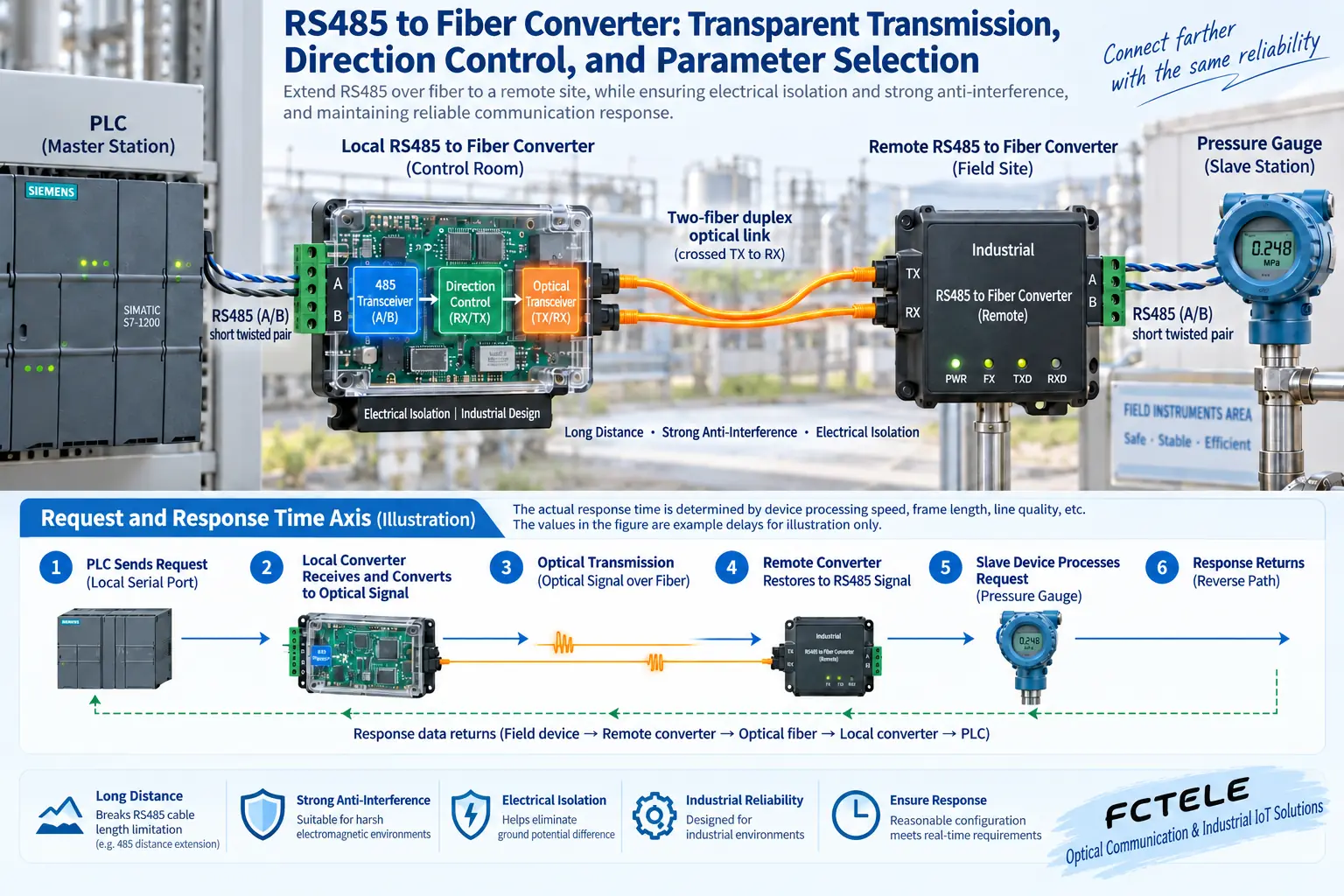
Two-wire RS485 is usually half-duplex; after the master sends a request, it must release the line to give the slave a chance to respond. The converter’s automatic direction control, buffering strategy, and switching timing must support the actual messages, especially short messages, continuous frames, and longer responses. Switching direction too late may block the beginning of the slave’s response, while switching too early may cut off local data.
Fiber propagation and device processing also take time, and the master timeout setting should cover transmission, conversion, slave processing, and the return process. Do not judge based only on the theoretical speed of light and assume there is no delay, and do not write all devices as having a fixed number of microseconds without measurement. Protocols such as Modbus RTU also have frame interval requirements, and it should be confirmed that the device’s processing method suits the project.
How to check the parameter table item by item
Both end devices should support the same baud rate, data bits, parity, and stop bits, and confirm the two-wire or four-wire form, wiring polarity, and reference ground requirements. The naming of A/B terminals may differ among manufacturers, so it should be checked against D+/D- or detailed definitions. For the optical port, check single-mode/multimode, single-fiber/dual-fiber, wavelength combination, and dedicated compatibility at both ends.
The local and remote ends each belong to an electrical segment, and termination resistors cannot be “counted as one bus” along the fiber. The bus trunk, short stubs, shielding, and grounding need to follow site regulations, and the termination position and resistance value should match the line; resistors cannot be added randomly at every node. The optical port distance and received power range also need to be checked.
Debugging starts with one instrument
First verify under a short copper line that the PLC and instrument can communicate correctly, then add a pair of converters and a short fiber, and finally replace it with the site link and gradually add nodes. Record the number of requests, timeouts, CRC errors, and response latency. Use the actual longest message and scan cycle for stress testing, and after power recovery confirm that direction control will not get stuck or the configuration will not be lost.
If the optical link is normal but the serial port times out, first check polarity, format, master/slave addresses, and direction timing; if errors appear as nodes increase, check the electrical segment wiring and load. In this way each step can locate a specific boundary.
Why does the polling cycle get longer with more nodes?
The master must send requests one by one and wait for responses, and any retry takes time. After adding an optical link, even if the data bits are completely correct, the increase in response time may make the original timeout setting unsuitable. The complete polling cycle should be estimated according to the number of nodes, the length of each message, and the slave processing time, and then verified with on-site statistics.
Do not mask line errors by endlessly extending the timeout. Recording which address the timeout occurs at, what type of command, and under what load helps identify a slow device, incorrect termination, or an occasional power supply problem. Being able to adapt to a rate range does not mean it is stable in any topology and number of nodes; especially long branches and too many terminations will change the conditions of the electrical segment.
Multipoint optical networks need a clear definition of the topology and data distribution method supported by the device. Ordinary point-to-point devices cannot be changed into arbitrary multi-station communication using only a passive optical splitter; the optical budget and control mechanism may both fail to meet the requirements. Ring or multipoint serial optical systems should be designed according to a complete plan to avoid multiple masters driving the half-duplex segment at the same time.
During maintenance, check the power supply and alarm records at both ends. Restarting the remote converter may allow the optical link to recover afterward, but the master or application may still be in an error state; acceptance should cover this recovery process. Safety-related control should not rely only on serial port timeout default values, and fault actions need to be set according to the complete system requirements.
References:TI: RS485 bus configuration and termination.
Translated from the Chinese technical article. Source first published: 2019-11-04. Source last revised: 2026-10-13T23:18:15+08:00. Read the Chinese source
