


Conclusion first: Sound quality cannot be judged only by connector shape. TOSLINK optical and coaxial mostly carry S/PDIF digital bitstreams; the key to compatibility is sample rate, channel format, and sending/receiving devices. RCA and XLR mostly carry analog audio; the key to stability is level, impedance, balancing method, cable, and grounding. XLR is not a “bigger RCA”; it usually uses differential reception to cancel noise picked up equally by two signal wires, making it more suitable for stages, conference rooms, broadcasting, and industrial sites.
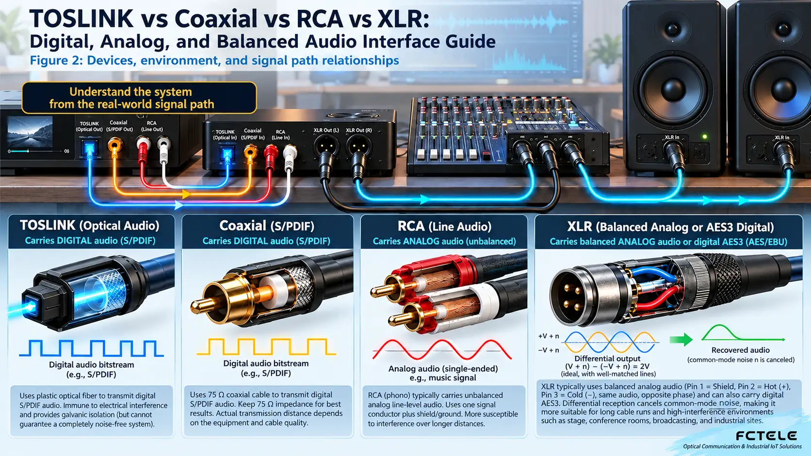
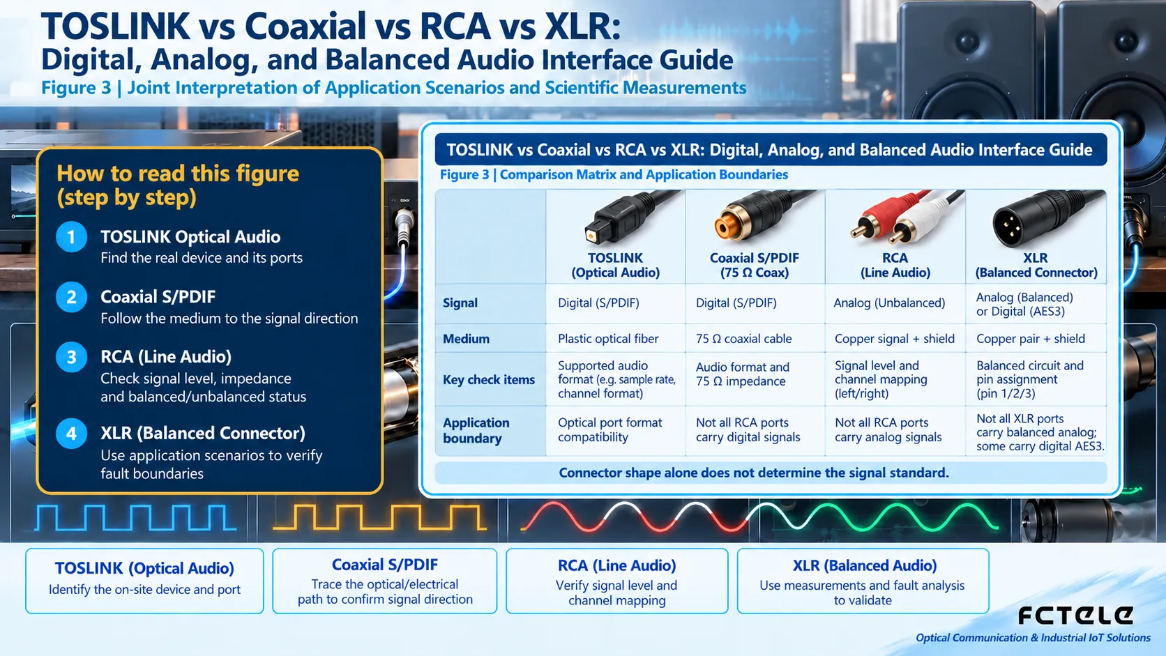
How to read the diagrams: This article centers on “TOSLINK vs Coaxial vs RCA vs XLR: Digital, Analog, and Balanced Audio Interface Guide” and uses the physical objects and system boundaries of TOSLINK, coaxial, RCA, and XLR, together with “TOSLINK, Coaxial, RCA, and XLR: The Role of TOSLINK Optical Audio in the Link,” to organize the illustrations. When reading, first confirm TOSLINK optical audio along the signal or state direction, then check boundaries with coaxial S/PDIF, and finally trace abnormal phenomena back to the specific connector, medium, or protocol layer.
1. Physical objects and system boundaries of TOSLINK, coaxial, RCA, and XLR
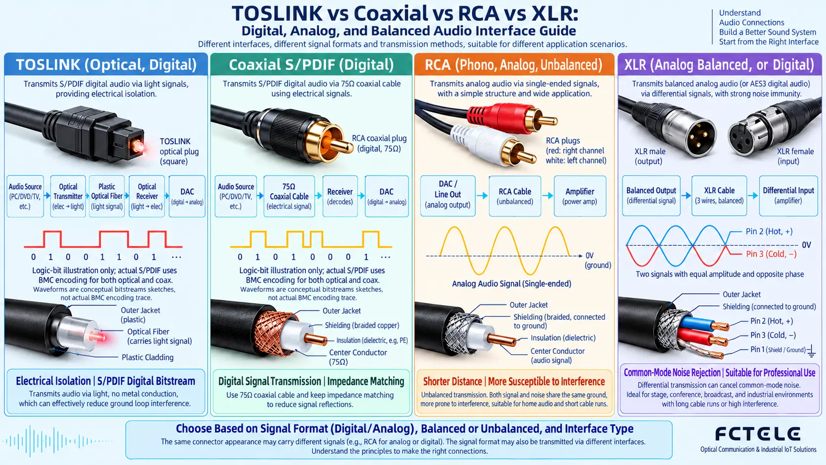
TOSLINK encodes digital audio into light pulses and transmits them through plastic or glass optical fiber. Both ends are electrically isolated, so no ground loop forms. It is suitable for digital connections between TVs, players, and amplifiers. Its limitation is not that “the sound is not good enough,” but the sample rate, channel count, and compressed formats supported by the transceiver chips and the S/PDIF link.
Coaxial S/PDIF also carries a digital bitstream, but it travels as an electrical signal in a 75Ω coaxial cable. Connectors are commonly RCA or BNC, so seeing an RCA shape does not mean it is an analog port; you must check the panel labels COAXIAL, S/PDIF, DIGITAL OUT/IN. Coaxial connections are secure and have sufficient bandwidth, but there is an electrical connection between devices, so ground potential differences must be considered in complex grounding environments.
RCA analog audio generally uses one plug per channel: white or black for left channel, red for right channel. It uses an unbalanced structure with a signal wire plus a shielded ground. It is simple to connect and widely compatible, suitable for short-distance connections inside racks or home devices; when lines are longer or there are inverters or high-power cables nearby, hum and electromagnetic interference are more likely.
2. TOSLINK, coaxial, RCA, and XLR: The role of TOSLINK optical audio in the link
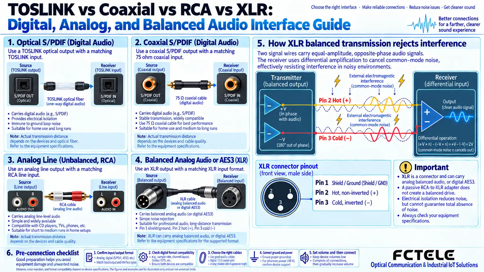
In a common three-pin XLR, pin 1 is shield/ground, pin 2 is hot (in-phase), and pin 3 is cold (out-of-phase). The sender turns the same audio into two signals of equal amplitude and opposite phase; external noise picked up along the cable adds to both wires in approximately the same direction. When the receiver calculates the difference between the two, the desired signal adds while common-mode noise cancels. This is the common-mode rejection principle of balanced transmission.
XLR also has a locking latch, shielded shell, and clear pin assignments, making it suitable for frequent plugging and long-distance wiring. But “using an XLR plug” does not mean the device internally has a true balanced circuit. When selecting, check whether the manual states Balanced, input/output impedance, nominal level, and maximum cable length. Microphone inputs may also provide 48V phantom power; before connecting a device that does not support phantom power, you must confirm the power status.
3. TOSLINK, coaxial, RCA, and XLR: Quantitative performance verification with coaxial S/PDIF
TV or set-top box to home amplifier: First check whether both ends support TOSLINK or coaxial S/PDIF, then verify formats such as PCM, Dolby Digital, and DTS; if either end does not support the target format, there may be no sound even if the connector fits. If using optical fiber, ground loops between TV and amplifier can be avoided.
CD player, DAC, and active speaker short-distance connection: If the device only has analog unbalanced ports, RCA can be used, connecting left and right channels correspondingly and keeping away from power cables. If the device has true balanced inputs and outputs, and the distance is long or the electromagnetic environment is complex, prefer XLR.
Stage, conference sound reinforcement, and broadcast systems: When long lines, multiple devices, lighting power, and amplifiers coexist, an XLR balanced link is usually more stable. Do not use a passive adapter to simply turn RCA into XLR and expect to gain balanced interference immunity; true conversion requires matching balanced driver/receiver circuits, isolation transformers, or professional DI boxes.
Cross-floor or strong electrical environment: If both the signal source and receiver support digital optical fiber, TOSLINK can provide electrical isolation; if the distance exceeds consumer fiber capability or multiple industrial audio channels are needed, choose a dedicated audio fiber optic transmission device and verify channel count, sample rate, latency, and optical interface.
4. TOSLINK, coaxial, RCA, and XLR: Infer fault location from abnormal phenomena
- Confirm whether the port is digital or analog; do not judge only by RCA, BNC, or XLR shape.
- Verify format, sample rate, channel count, level, and impedance at both sending and receiving ends.
- Wire XLR as pin 1 ground, pin 2 hot, pin 3 cold; pin definitions at both ends must match, and the shield should be handled according to the system grounding plan.
- Route audio cables separately from power cables; when crossing, try to cross perpendicularly and avoid long parallel runs.
- First verify section by section with short cables, then add the final cables; separately check for no sound, clipping, noise floor, hum, and left/right channels.
1. First unify the comparison basis: TOSLINK, coaxial, RCA, and XLR
Is XLR definitely better sound quality than RCA?
Not necessarily. In short-distance, low-interference environments, both can achieve good results. XLR’s main advantages are balanced transmission, locking latch, and interference immunity; final sound quality still depends on circuits, cables, and device matching.
Can an RCA-to-XLR cable turn an unbalanced signal into a balanced signal?
Usually not. Simply changing the connector does not generate a pair of in-phase and out-of-phase signals; a balanced driver circuit, DI box, or isolation transformer is needed to gain the true advantages of balanced transmission.
Is optical sound quality definitely better than coaxial?
Not necessarily. When both carry the same digital format, differences depend more on transceivers, clock recovery, DAC, and overall design. Optical’s clear advantage is electrical isolation.
What are pins 1, 2, and 3 on XLR?
The common AES/IEC convention is pin 1 shield ground, pin 2 hot in-phase, pin 3 cold out-of-phase. When repairing or mixing with old equipment, still verify the device manual.
Translated from the Chinese technical article. Source first published: 2022-02-11. Source last revised: 2026-10-13T23:36:13+08:00. Read the Chinese source
