


The indicator lights on a multi-service fiber optic transmission device should be judged in four layers: power, optical path, services, and alarms. Names such as PWR, OPT, LINK, ACT, and ALM are common, but the meanings of colors, steady light, and blinking are defined by the model. An optical link light being on does not mean that every telephone, serial port, or Ethernet service has passed; acceptance testing still requires testing each one separately.
First find the light meaning table for this device
Record the complete model, panel labels, and current state, then check the manual for the corresponding version. Do not use the six-light explanation for a fiber optic transmission device to explain another telephone or E1 fiber optic transmission device. Some lights indicate the presence of an optical signal, some indicate frame synchronization, and some indicate service activity; similar names may also represent different conditions.
Red is often used for alarms, but you cannot use “a red light definitely means damage, and a green light definitely means normal” as a universal judgment. Blinking may be data activity, or it may be an alarm code; only a combination of multiple lights may point to a specific state. Short displays during device startup self-test should also be distinguished from the state after operation is stable.
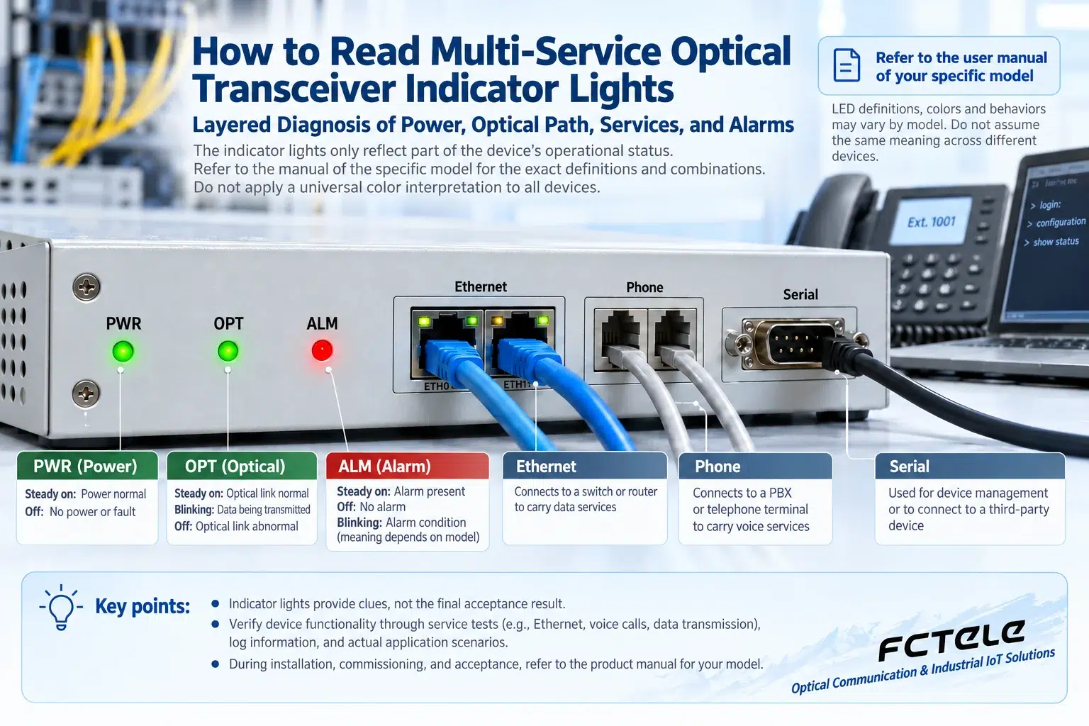
Power light: the first step in confirming the power supply chain
When PWR is off, check the power input, terminal polarity, adapter or power module, and upstream protection device. Measuring only the no-load voltage may not reveal a drop under load. When necessary, have qualified personnel measure the power supply while the device is operating. Do not casually short terminals while powered or replace modules that do not support hot swapping.
A dual-power device may have two input status lights, or it may use a single light to indicate overall power supply. If one path fails and the device continues to run, that does not mean the alarm has no value; it may indicate that redundancy has been lost. Recording the two power supply sources is the only way to assess whether there is a common single point.
Optical path light: whether there is light and whether synchronization is possible are different
OPT or a similar light may indicate optical signal detection or optical link status. If it is off, check the pairing at both ends, fiber type, wavelength, transmit and receive direction, and connectors, then measure optical power. For dual-fiber, TX should connect to the opposite end’s RX; for single-fiber BiDi, the transmit and receive wavelengths at both ends should be complementary. You should not judge whether the optical port is emitting light by looking directly into it.
Having light does not mean correct data is being received. If the rate, protocol, or module pairing is incompatible, optical power may be present but an effective service channel cannot be established. The received power must also be within the allowed range; both too weak and too strong can cause problems, and you cannot apply one fixed dBm pass value to all devices.
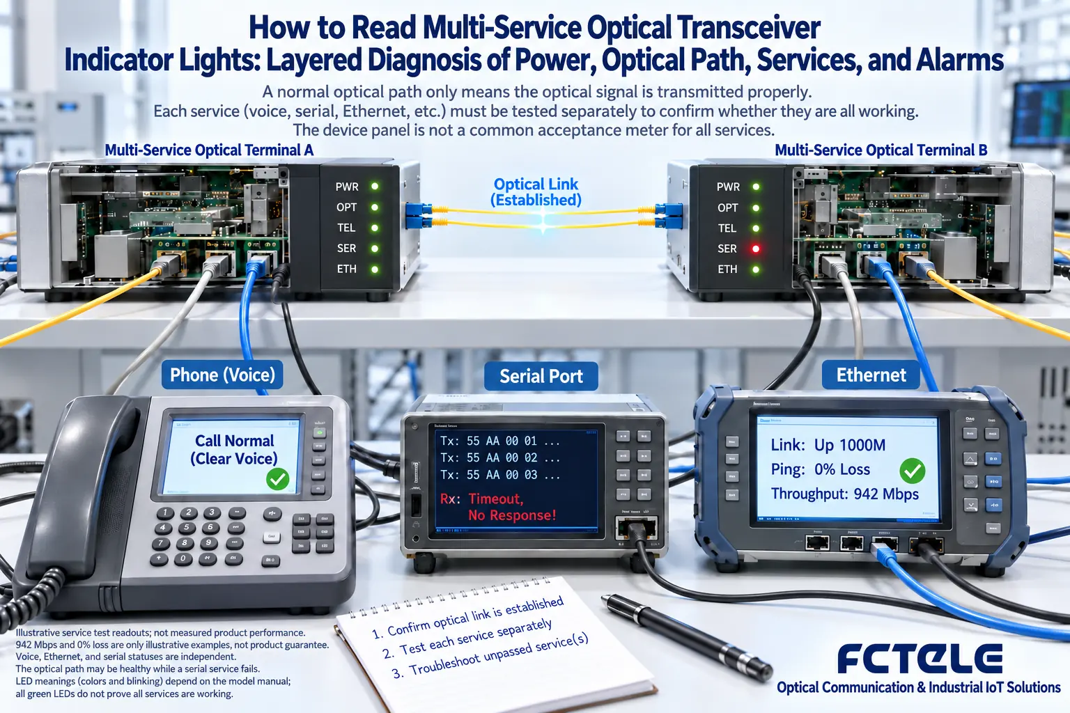
Service lights: check each interface one by one
Ethernet LINK is usually related to link establishment, and ACT is usually related to transmit and receive activity, but the specific light meanings are still subject to the manual. Blinking indicates that activity may exist; it does not mean that VLAN, IP address, or application services are necessarily correct. You need to combine port status, packet loss, and actual application testing.
For telephone services, check the FXS/FXO role, on-hook/off-hook, dialing, ringing, and two-way conversation; for serial port services, check the electrical interface, baud rate, frame format, and address; E1 services also involve line alarms, framing, and clocking. DATA not blinking may also mean there is currently no service, and it is not necessarily a fault. Do not modify production configuration just to make the light blink.
How alarm lights help narrow the scope
Indications such as ALM, FAULT, or service LOS should be interpreted together with alarm records. Check whether they belong to the optical path, input branch, power supply, or internal device status, and compare information from both ends. When only one branch is abnormal, check that service’s input and interface first; there is no need to immediately replace the entire device.
During maintenance, take photos to save the light state, time, and service symptoms, then record each operation and result. Perform non-destructive checks first, and carry out necessary loopback, fiber removal, and replacement tests during an approved window. After recovery, not only check whether the alarm has disappeared, but also retest the services and establish a normal baseline, so that the next abnormality can be located more quickly.
Translated from the Chinese technical article. Source first published: 2023-11-13. Source last revised: 2026-10-13T23:07:12+08:00. Read the Chinese source
