


When industrial switches use SFP optical ports to connect factory areas, tunnels, substations, and roadside cabinets, engineers often select optical modules based on the “nominal transmission distance.” But whether the link can remain stable over the long term truly depends on whether there is enough margin between the transmit optical power, the receive sensitivity, and all the losses along the way. Two fibers with the same distance may perform completely differently because of connectors, splicing quality, bend radius, and end-face contamination.
The optical port lighting up does not mean the link quality is qualified. When the received power is close to the sensitivity boundary, the device may experience intermittent disconnections and bit errors after temperature changes, slight cable disturbance, or further end-face contamination. Therefore, SFP selection, link budget, construction acceptance, and operation and maintenance measurements should form a closed loop.
1. What conditions should be checked first when selecting an SFP optical module?
The rate must match.The rate supported by the switch port and the optical module rate should be consistent. Compatibility cannot be judged only by identical appearance. It is also necessary to check whether the port supports the corresponding module type and management information reading.
Single-mode and multimode cannot be mixed.Multimode fiber is suitable for corresponding multimode modules, and single-mode fiber uses single-mode modules. When the fiber core and light emission conditions do not match, even if short-distance communication occasionally works, it should not be considered a qualified solution.
Wavelength and single-fiber/dual-fiber must be paired.A dual-fiber link uses one core for transmitting and one core for receiving, and the modules at both ends usually use matching wavelengths. A single-fiber bidirectional module uses different transmit and receive wavelengths on the same core, and the two ends must be a complementary pair. It is also necessary to check interfaces such as LC and SC and the patch cord type.
2. How is the optical link budget calculated?
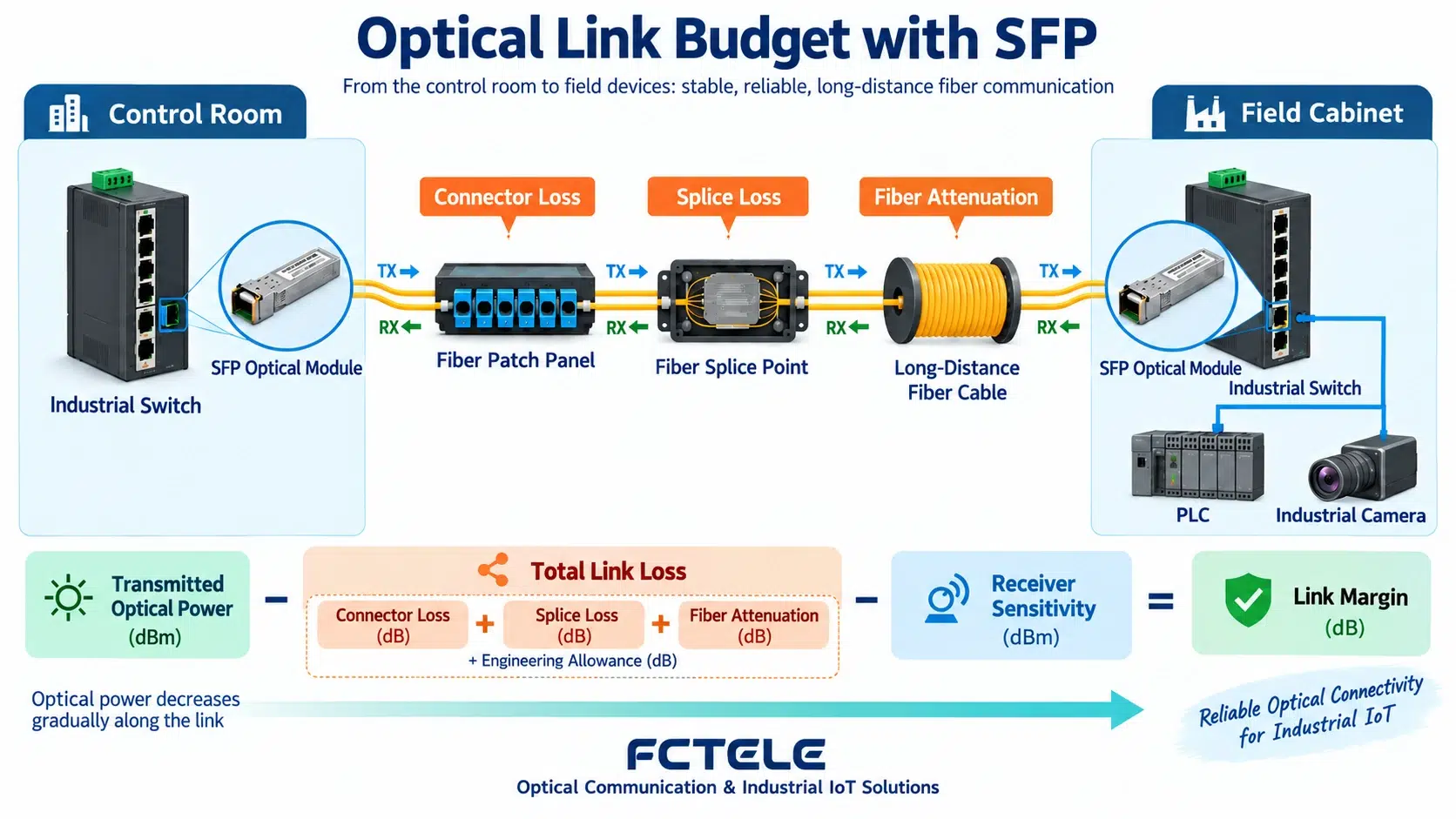
The available optical power budget can be understood as the difference between the allowable output at the transmitting end and the minimum receivable capability at the receiving end. The total link loss includes attenuation caused by fiber length, connector insertion loss, splice loss, and losses from splitters or other passive components. After subtracting the total link loss from the available budget, the remainder is the engineering margin.
The engineering margin is used to absorb light source aging, temperature drift, additional splices during repairs, and changes in end-face condition. The theoretical budget must not be fully used up. During the design stage, calculations should be based on the formal technical data of the selected module and fiber, and empirical values from other models should not be applied. After construction is completed, actual measurements should be used for verification with an optical power meter or OTDR.
3. Why can excessively strong received power also be a problem?
When using high-power, long-distance modules over short distances, the receiving end must not only avoid excessively low power but also prevent exceeding the allowed overload range. If the measured received power is too strong, whether appropriate optical attenuation measures are needed should be evaluated based on the module data, rather than reducing power by artificially bending the fiber. Bending brings unstable and uncontrollable loss.
4. Key details of on-site construction and acceptance
Before inserting patch cords, standard tools should be used to clean and inspect the end faces. Caps cannot replace cleaning. For dual-fiber links, confirm the Tx and Rx polarity, and the labels in patch panels and splice boxes should be consistent with the port ledger. The fiber bend radius, pulling tension, and protection should meet construction requirements, avoiding cabinet door squeezing or cable ties being too tight.
During acceptance, record the module models at both ends, wavelength, serial information, transmit and receive optical power, link length, number of splice points, and test time. For ring network or dual-uplink projects, each path should be measured separately, and it is not enough to verify only the currently forwarding link.
5. How to troubleshoot when the optical port does not light up or drops intermittently?
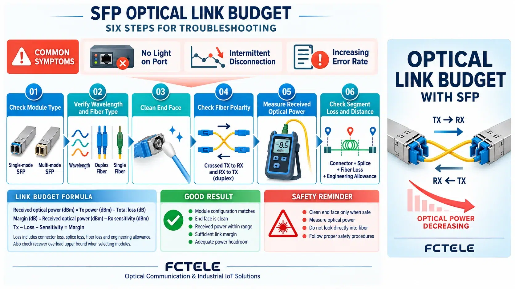
Step 1: check single-mode, multimode, rate, and device support; Step 2: check wavelength and single-fiber/dual-fiber pairing; Step 3: clean connector end faces; Step 4: check dual-fiber polarity and patch cords; Step 5: read or measure the transmit and receive optical power at both ends; Step 6: use segment replacement or OTDR to locate abnormal loss. Record the results at each step to avoid repeated insertion and removal causing new contamination.
If the optical power is normal but bit errors still occur, continue checking port negotiation, module temperature, power supply, fiber reflection, and device logs. If it recovers after replacing the module, also check the parameters of the old and new modules, and do not conclude that the original module is damaged based only on the symptom.
6. How are Feichang Technology products used in fiber access solutions?
Feichang Technology’s industrial fiber optic switch product series cover multiple access forms such as fixed optical ports and SFP optical ports. Some product information on the official website clearly lists support for single-mode dual-fiber, single-mode single-fiber, and multimode dual-fiber transmission methods. During project selection, port rate, interface, wavelength, optical power, and transmission distance should still be checked item by item for the specific product, and parameters should not be referenced across models.
Conclusion
A reliable industrial fiber link is not “pass if it lights up,” but rather matching medium and module, having a basis for loss calculation, sufficient engineering margin, clean construction end faces, and traceable actual measurement records. Moving this work forward to the design and acceptance stages can significantly reduce intermittent disconnections that are difficult to reproduce after commissioning.
Translated from the Chinese technical article. Source first published: 2026-09-12. Source last revised: 2026-10-13T23:36:13+08:00. Read the Chinese source
