


The reliability of an industrial switch is not determined by a “metal housing,” an “old brand,” or a single wide-temperature number alone. Long-term stability comes from the coordination of power supply, heat dissipation, interface protection, firmware behavior, and maintenance mechanisms. When evaluating a specific product, you should focus on how it works under the planned load and on-site environment, how it reports faults, and how it restores services.
Translate “reliable” into things that can be observed on site
When a site says “the switch is unreliable,” it may mean sudden power loss, unstable negotiation on a certain port, slow ring recovery, or it may simply be contaminated fiber connectors causing bit errors. Only by classifying faults first can you determine whether the problem comes from the overall hardware, configuration, software, or an external link. Attributing all abnormalities to a “bad brand” will instead cause you to miss the real cause.
Reliability also does not mean never failing. After a device fails, being able to raise an alarm as soon as possible, let a backup link take over, and make replacement and configuration recovery convenient are also related to service availability. A cheap device that is difficult to troubleshoot may bring higher operation and maintenance costs; a model with many features may also increase the risk of misconfiguration if the team does not know how to manage it.
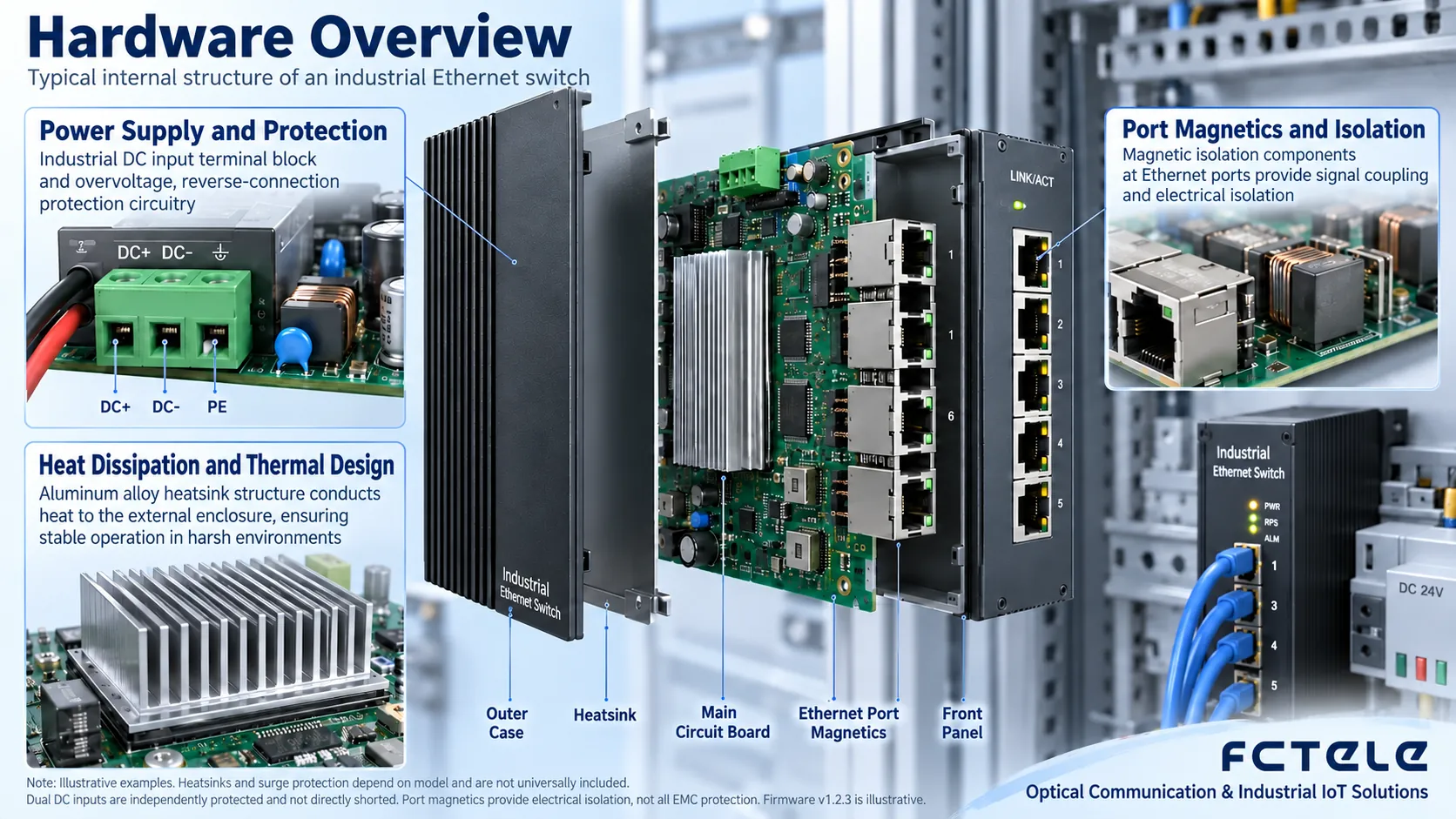
Power supply and temperature rise: the conditions most easily hidden by the chassis appearance
For DC input, check the voltage range, positive and negative poles, power margin, and grounding requirements. On-site power may fluctuate due to other equipment starting and stopping, and poor line contact can also cause instantaneous voltage drops. You should record the actual voltage at the switch end, not just look at the power supply nameplate. For devices with two inputs, the switching method and alarm behavior must be clearly defined; splitting two wires from the same power source does not eliminate the single point of failure of the power source itself.
Components inside the switch consume power and generate heat, and the heat needs to be transferred to the environment through heat sinks, the housing, or fans. Fanless does not mean “no heat,” but rather relies on natural convection and conduction for heat dissipation. Full-port traffic, high-power optical modules, or PoE loads may all increase temperature rise. When installed in a sealed control cabinet, you should look at the actual intake air temperature and installation spacing, and you cannot directly equate a laboratory room-temperature test with the hottest on-site condition.
Lifespan and MTBF are also not the same thing. MTBF usually describes statistical failure characteristics under a specific model and conditions. It is not a promise that a particular unit will necessarily be used for that many years, and it certainly cannot be simply converted from an hour count into a user warranty period. When comparing reports, look at the calculation method, temperature, component configuration, and maintenance assumptions. Without these conditions, an impressive large number cannot support your project judgment.
Interface protection is not the magic of “isolating everything”
Copper ports, optical ports, and power ports face different risks. Copper cables may introduce interference and surges into the device. Fiber does not conduct current and can reduce electrical coupling between the two ends of the link, but the switch still needs local power, and the power and grounding paths may still be subject to interference. Using fiber cannot replace a complete lightning protection, grounding, and power protection design.
Test reports should correspond to the model, ports, and specified conditions. Passing a certain immunity test means that the corresponding criteria are met under the conditions of that standard; it does not mean the device can withstand lightning of any strength. On-site grounding, shielding, cable routing, and protector selection will also change the results; these tasks should be carried out by professionals according to project specifications and equipment instructions.
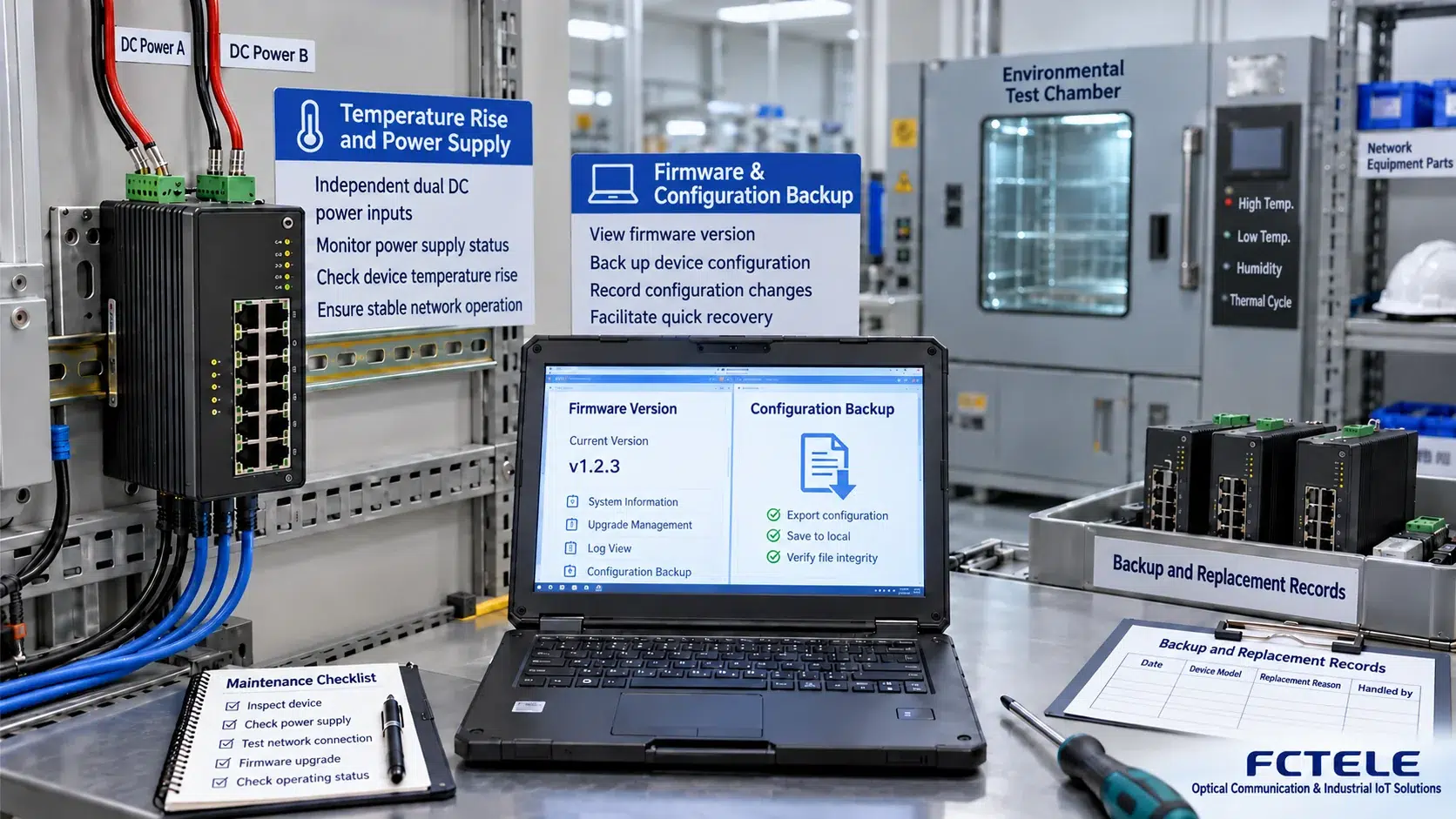
Firmware and operations: invisible, yet able to determine downtime
Network management functions let engineers know whether a port is down, whether there are bit errors, and whether temperature or power is abnormal, but the premise is that alarms are configured correctly, time is consistent, and someone checks the logs. You should configure the management methods allowed by the project, change default credentials, disable unnecessary services, and restrict management access. Just because a switch is connected to the network does not mean any computer should be able to modify its configuration.
Before upgrading firmware, first check the applicable hardware version and release notes, back up the configuration, check key services on a sample unit, and then schedule a maintenance window. You cannot directly upgrade a production network just because it is a “new version,” nor can you forever refuse updates and ignore known faults and security issues. Keeping the previous version and a recovery method helps keep upgrade risk within a manageable range.
Spare units must be verified. Another model with the same number of ports may have different VLAN defaults, ring implementations, or optical module compatibility boundaries. When purchasing spare parts, check power supply, installation, firmware, and configuration migration, and conduct a replacement drill in advance. Temporarily finding a device that “looks the same” during a fault often takes longer than a planned replacement.
How do you write a meaningful reliability acceptance record?
First write the business objectives, for example, “video will not be continuously interrupted due to a single uplink failure” or “it can still run after one input loses power,” and then design corresponding tests. Cover planned load, port negotiation, continuous communication, power switching, and link recovery, and record temperature, time, firmware, and device configuration. Service interruption time, packet loss, and recovery results should be recorded separately, not just written as “normal.”
When an abnormality occurs, save logs and port counters, and replace items one by one with known-good power supplies, short cables, and optical modules, avoiding changing multiple conditions at the same time. Observe whether the problem follows the device or follows the port, cable, or environment. This troubleshooting method allows suppliers to reproduce the issue faster and also avoids misjudging on-site cabling problems as overall device quality problems.
Feichang Technology products should likewise demonstrate their capabilities through specific model documentation and project testing. This article does not use “old brand” as a substitute for evidence, and does not give reliability scores without measurement basis; the components and scenarios in the diagrams are mechanism explanations and do not constitute a promise regarding the lifespan, certification, anti-interference level, or fault recovery time of any model.
Translated from the Chinese technical article. Source first published: 2019-07-18. Source last revised: 2026-10-13T23:45:12+08:00. Read the Chinese source
