


One-fiber multi-port devices usually connect multiple electrical ports to the same switching fabric, then uplink through the optical port. Whether VLANs can be divided, port-to-port communication can be restricted, or truly independent data channels can be provided depends on the internal structure and functions. Logical isolation depends on configuration, while physical separation depends on actual hardware boundaries. You cannot claim that two networks are already physically isolated just because fiber is used.
Multiple electrical ports may share the same switch chip
Common one-fiber multi-port devices perform Layer 2 switching; they do not provide an independent optical line for each electrical port. Multiple terminals share the uplink bandwidth and device resources, so you need to confirm each port’s rate, uplink capacity, and forwarding capability. If electrical ports must not communicate with each other, the port isolation function must be clearly specified. If different services need to be grouped, VLAN support must be clearly specified. Ordinary unmanaged devices may not have these configuration options, and you cannot infer them from the number of ports.
The electrical isolation of fiber is not the same as network isolation
Fiber does not connect the two ends through a conductor, which can reduce the effects of ground potential differences and certain electrical interference, but it still transmits data. Ethernet devices at both ends can communicate normally, and malicious or erroneous packets can also reach the other end along this link. Electrical isolation, data access control, and physical network separation are different issues. A product whose name includes isolation should explain whether it isolates power, interface electrical characteristics, port forwarding, or the complete service channel.
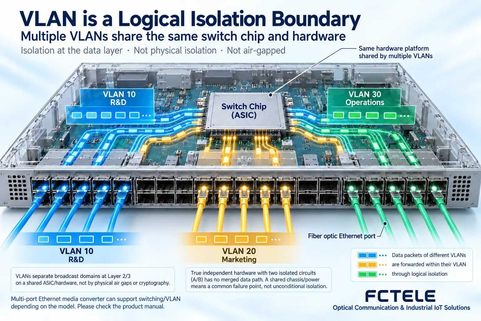
VLANs divide logical boundaries, but resources can still be shared
VLANs group Layer 2 networks. When configured correctly, different groups do not directly communicate at Layer 2; after routing or other channels, they may still access each other according to rules. The processor, power supply, firmware, and management entry point of shared equipment are not separated, and configuration errors or device failures may affect multiple groups. Therefore, VLANs are suitable for clear logical partitioning needs, but they cannot be treated as proof of hardware isolation with no shared resources, nor as an encryption mechanism.
Physical separation must be reviewed along the complete path
If two networks must be separated at the physical layer, check whether the terminals, switching equipment, lines, management connections, and uplinks are truly independent; do not look at only one segment of cable. Independent ports or independent fiber cores may also eventually converge on a common switching device. For products that share a chassis but have independent internal channels, the architecture, testing, and applicable boundaries must be clearly specified. When specific security standards are involved, formal requirements and verification materials should be used, not conceptual substitutes.
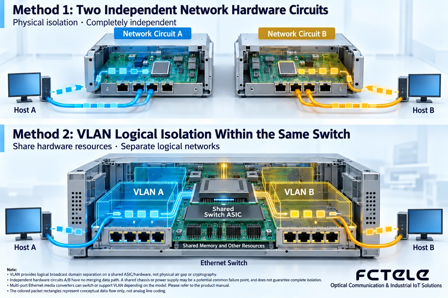
Write isolation requirements as testable conditions
For example, specify which terminals are allowed to communicate, which are prohibited, who has management access, and whether failures are allowed to affect multiple parties together, then choose the device structure and configuration. Acceptance testing should confirm that allowed paths work normally and also attempt prohibited paths, and check behavior after power loss, recovery, and configuration reset. Save the topology, port table, and configuration backup. Terminological debate is less useful than an executable test checklist, but test results also cannot replace the formal certifications required by the requirements.
Example: A production network and a maintenance network share one device
If the project allows logical isolation, two groups can be established according to clear port and VLAN configurations, then unauthorized access and management boundaries can be verified. However, it should be truthfully stated that the two groups share power, a switch chip, or a management system, and this must not be written in delivery documents as completely independent hardware. If failures must not affect each other or formal physical separation is required, the shared structure needs to be reevaluated, possibly using independent devices and lines. Even if two fiber cores are used, the backend common uplink may converge again; the complete path from terminal to uplink must be consistent with the isolation requirements.
Translated from the Chinese technical article. Source first published: 2019-07-25. Source last revised: 2026-10-13T22:50:44+08:00. Read the Chinese source
