


A fiber optic transmission device is used to send specific service signals into optical fiber and restore them at the other end as the required interface. Video, audio, telephone, serial and Ethernet products do not process signals in the same way. The key to choosing a fiber optic transmission device is not only asking how far it can transmit, but first determining the service signals at both ends, the interfaces, and whether encoding or multiplexing is needed.
Fiber is the medium; the service interface is the starting point
A camera may output analog video, SDI, HDMI or an IP network stream. Although all are called video, they cannot be directly connected to the same type of port. Telephones, RS485 instruments and Ethernet computers also have different electrical and protocol requirements. A fiber optic transmission device must first accept the correct service format and then perform appropriate processing.
Some devices mainly convert electrical signals into optical signals, while some devices also perform encoding, multiplexing or protocol processing. The fact that it has an optical port does not mean it can mix and transmit any signal; multi-service devices also need each interface, channel and carrying capacity to be clearly defined.
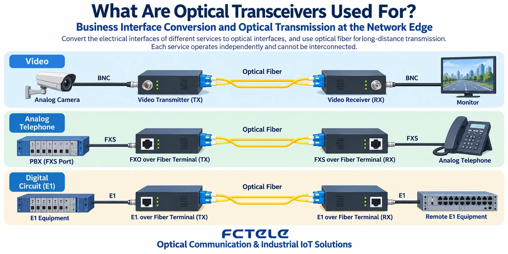
Why does it need a transmitter end and a receiver end?
The transmitter end processes the received service into a transmittable signal and drives the optical transmitter; the receiver end obtains the signal from the optical receiver and restores the service. One-way video equipment may have a clear transmitter end and receiver end, while two-way telephone or data equipment often has both sending and receiving capabilities at the same time.
Single-fiber bidirectional products distinguish directions by different wavelengths, while dual-fiber products usually use two fiber cores. Single fiber does not equal one-way, and the transmitter end does not necessarily mean the device cannot receive other services at all. To judge direction, look at the specific service channel, not just the device name.
Several scenarios where it is easy to buy the wrong thing
The coaxial video signal of a traditional analog camera cannot be extended using only an ordinary Ethernet fiber media converter. An HDMI picture also cannot be assumed to be a standard network product just because a network cable is used; some extenders use a proprietary electrical line method and cannot be connected to an ordinary switch.
An ordinary analog telephone needs the correct FXS or FXO role, while a serial port requires checking RS232, RS422 or RS485 and the terminal definitions. An operator’s PON optical modem also involves the PON standard and authentication, and cannot be interchanged with an ordinary point-to-point service fiber optic transmission device just because the optical port looks similar.
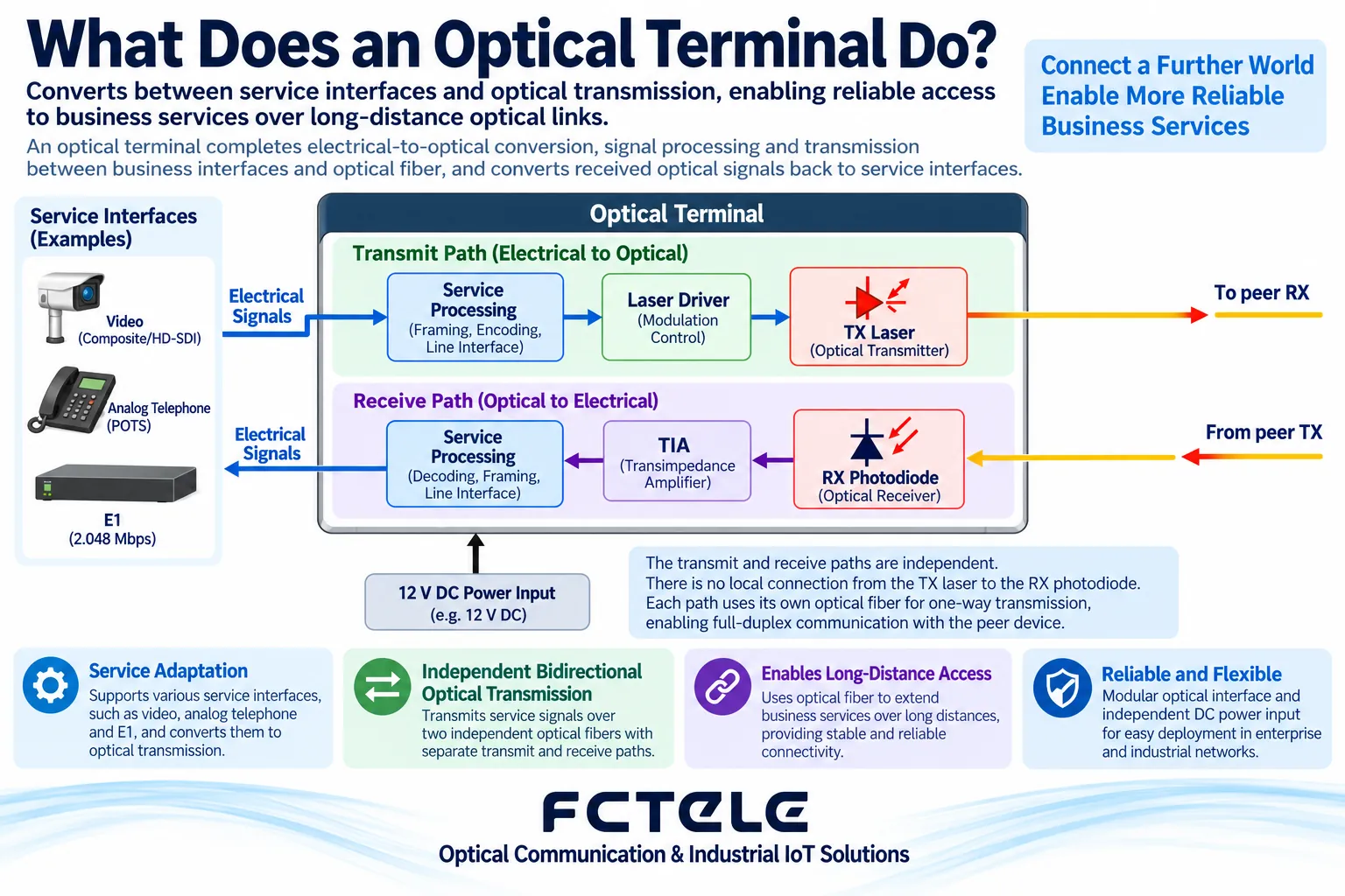
Besides distance, what other parameters should be considered?
The fiber type, wavelength and receiving range must match. The optical power budget must include the fiber core, connection points and maintenance margin, and overload conditions must also be checked. The length, bending, end-face contamination and splice loss of the on-site line can all make actual performance different from the ideal distance.
On the service side, confirm the resolution, bit rate, audio format, number of telephone lines or serial parameters, and also state the number of services carried at the same time. A nominal claim of supporting a certain interface cannot directly lead to the conclusion that it supports all versions, all formats or all maximum modes of that interface.
Installation location changes reliability requirements
The temperature, power supply and protection of an outdoor equipment cabinet and a control room rack are different. Check the device operating conditions, installation heat dissipation and grounding. Cable entry into the cabinet also needs to consider waterproofing and mechanical stress. The fact that the fiber link has no long copper line running through it does not mean the power supplies and enclosures at both ends no longer need protection.
A centralized rack can reduce maintenance complexity, but the backplane, power supply and management module may become common failure points. For important services, state which channels are affected by a single module failure and by a power failure respectively, and arrange spare parts or redundancy according to the actually acceptable interruption.
Put acceptance testing on the service terminals
For video projects, observe the real picture, picture switching and continuous recording; for telephone projects, test ringing, two-way voice and hanging up; for data projects, test real commands, timeouts and recovery. The optical port light being on is only part of the link evidence and cannot replace the above terminal results.
Before selection, organize five pieces of information: “equipment at both ends—interface format—number of channels—fiber conditions—on-site environment.” For related classification, you can read fiber optic transmission device Type Description; procurement and acceptance are still subject to the specific model documentation and on-site joint debugging.
Translated from the Chinese technical article. Source first published: 2019-07-29. Source last revised: 2026-10-13T22:50:44+08:00. Read the Chinese source
