


Whether an industrial switch can work stably on site for a long time does not depend only on whether the label says ‘industrial grade’. The same device placed in a ventilated indoor cabinet and in a sealed box exposed to the sun may face completely different temperature, power and interference conditions. You can think of it as an electronic device that is always working: the chip generates heat, the power supply has an allowed range, and the ports need protection. Here we start from how heat gets out, how electricity gets in, and how interference reaches the ports, so that environmental requirements become conditions you can understand and check.
Temperature should be measured around the device, not just by looking at the weather
Imagine putting a computer in a closed small cabinet in summer. Even if the outdoor temperature has not exceeded the computer’s specification, the inside of the cabinet may keep getting hotter. The same is true for a switch: the surrounding power supply, PoE load and other devices generate heat together, and how much heat the cabinet can carry away determines the local air temperature. The device’s operating temperature is not the chip’s internal junction temperature; there is also a difference caused by heat transfer between them. For beginners, the first thing to measure is the real conditions around the device installation location, and then check the manual together with the load, not just copy the local weather forecast’s highest and lowest temperatures.
The operating temperature in a data sheet usually has specified installation and load conditions. You should find out whether it limits optical modules, PoE power or installation direction. The key on site is the cabinet air temperature around the device. Sunlight, nearby power supplies, sealed enclosures and dust accumulation can all cause local temperature rise. A wide-temperature rating does not mean no derating is needed under all operating conditions. First record the expected minimum and maximum temperatures, humidity and possible condensation, then check the product instructions; do not treat the temperature range of a single series as a common standard for industrial switches.
Fanless heat dissipation also needs a heat transfer path
Figure 1 shows the heat path: the chip generates heat, which passes through the thermal interface and structure to the metal enclosure, and then is dissipated to the surroundings by air flow and other means. A warm metal enclosure can mean heat is being transferred outward, and does not necessarily mean the device is broken; what really matters is the allowed temperature and operating status. Fanless devices rely on suitable installation direction, space and environment. When the heat sink is blocked or pressed against other heat sources, heat cannot easily get out. It is like a cup placed in a quilt: it does not cool easily. A thicker enclosure cannot replace the heat dissipation path of the whole cabinet.
The heat generated by the chip and power supply is transferred through the structure to the enclosure, and then carried away by the surrounding air. The metal enclosure, thermal materials, heat sink and installation direction together affect thermal resistance; a warm enclosure does not necessarily indicate a fault. Keep the top, bottom, left and right spaces according to the installation manual, and do not place the device against a heat-generating power supply or cover the heat sink. If the cabinet ventilation is insufficient, deal with the heat load of the whole cabinet; simply increasing the number of switch ports or replacing optical ports cannot solve heat accumulation inside the box.

Power supply adaptation range and redundancy are two different things
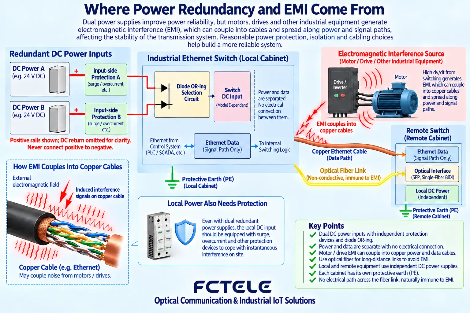
The power supply can be compared to the entrance through which the device gets energy, but it has allowed voltage and power conditions. Input that is too low, wires that are too thin, or poor contact at connectors can all cause power loss during startup or load changes. If dual inputs pass through a supported selection circuit, one path may continue to supply power when the other fails; Figure 2 explains this logic, not a specific wiring diagram. When both wires come from the same power supply, having two wire ends does not mean having two power supplies. Redundancy also depends on the supply path, fault alarms and service performance during switching.
Check the input voltage range, polarity, startup current and supply wire gauge. On site, power supply voltage drop and transient fluctuations should also be considered. Dual inputs may provide redundancy, but connecting both paths to the same power supply cannot protect against failure of that power supply. Whether different inputs are isolated, how alarms operate, and whether power loss on one path interrupts service should be checked in the documentation and tested. PoE models must also include the terminal load in total power and temperature derating; do not choose a power supply based only on the switch’s own power consumption.
Grounding and interference immunity cannot be guessed from names
Cables near motors and variable frequency drives may be affected by rapidly changing electric or magnetic fields, and interference enters the communication system through coupling, grounding or the power supply path. Shielding, reasonable routing, grounding and protection each have their uses, and none should be treated as a universal cure. The fiber optic section does not directly connect the two ends with a metal conductor, which helps avoid certain paths; but the device’s local power supply, copper ports and other connections may still be affected. Ordinary users should not change protective grounding or test with power on by themselves. It is more helpful to record when interference occurs, what the device does, and the power supply status.
Protective grounding, shielding and surge protection each have their roles and should be implemented according to the device and engineering specifications. Motors, variable frequency drives, high-current lines and copper cables crossing buildings may introduce interference or potential differences. Routing paths should be reasonable and the corresponding test conditions should be checked. Passing a certain electromagnetic compatibility test does not mean the device will not be damaged under any lightning strike or wiring error. Fiber optics can avoid a link conductor connecting both ends, but the local power supply and copper ports still need protection; grounding or surge measures cannot be cancelled because of this.
Installation protection and network functions must be confirmed at the same time
The so-called industrial environment also includes humidity, dust, vibration and possibly corrosive media, and cannot all be summarized by one wide-temperature specification. Condensation can create leakage paths where there should be no connection, dust accumulation can affect heat dissipation, and continuous vibration tests the installation and connectors. Protection ratings and material suitability should be supported by specific documentation. On the other hand, a device with a suitable environment may still fail due to network configuration errors: broadcast storms, uplink congestion, multicast configuration or service timing are not things that can be solved by switching to a metal enclosure.
DIN-rail, wall-mount or rack installation should match the structure and maintenance space. Ordinary industrial switches often need to be placed in a suitable cabinet. Whether they are waterproof, dustproof, corrosion-resistant or suitable for hazardous environments must be checked against clear ratings and evidence. On the network side, check port speed, uplink capacity, multicast, VLAN and the required redundancy protocols; being able to connect a PLC does not mean real-time performance is already satisfied. Environmental reliability and service forwarding capability are two dimensions, and you cannot just test whether it can be pinged after power-on.
Example: control cabinet renovation near a variable frequency drive
When troubleshooting link disconnections next to a variable frequency drive cabinet, you can first record the pattern: does it happen only when the motor starts, or all day when the temperature is high? The former suggests that power supply transients or coupling need to be checked, while the latter suggests that temperature rise or load conditions need to be checked, but these are only troubleshooting directions, not conclusions. Align network error counters, link logs and on-site action times to gradually narrow the scope. Before replacing equipment, save the original state and configuration so you can compare which condition change was effective. Operations involving protection, power or high-voltage cabinets must follow on-site safety rules.
First measure the cabinet temperature and power supply conditions, arrange a reasonable DIN-rail position for the switch, and separate communication cables from strong interference lines. Run with actual PLC and monitoring traffic, and record port error counters, packet loss and temperature; verify single-path power interruption and recovery during a safe maintenance window. If the link disconnects only when the motor starts, check both power supply transients and electromagnetic coupling, and do not first assume insufficient bandwidth. At handover, save wiring diagrams, configurations, environmental records and device models for later comparison.
Common misconception: do wide-temperature devices not need a cabinet and heat dissipation?
Not true. Wide temperature only describes the applicable range under specified conditions. Whether it is waterproof, whether it is suitable for outdoor use, what clearance is needed and how to derate are other requirements. When selecting, write out the actual environment, power supply, installation, network load and maintenance method separately, and then verify against the corresponding model’s manual. Project acceptance should also record these conditions; otherwise, if PoE load is added later or the device is moved to another cabinet, the original test conclusions may no longer apply.
Principle reference:Official technical materials. This article explains general mechanisms. Actual parameters are subject to the corresponding manual and test results.
Translated from the Chinese technical article. Source first published: 2019-07-30. Source last revised: 2026-10-13T22:50:44+08:00. Read the Chinese source
