


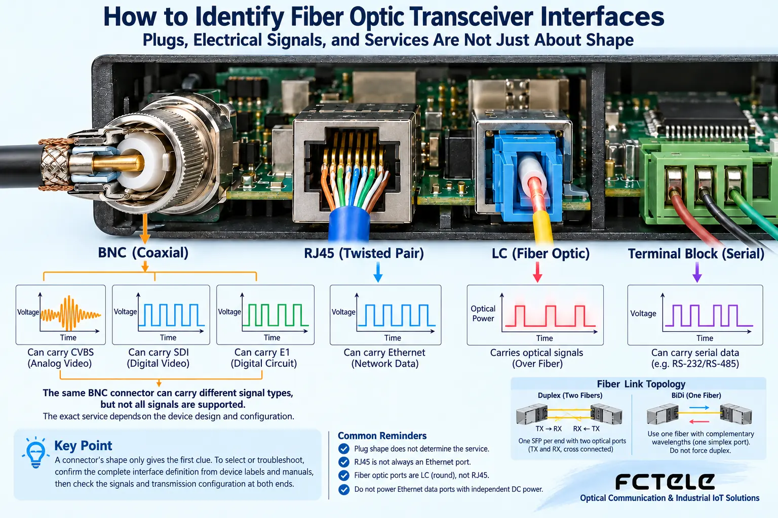
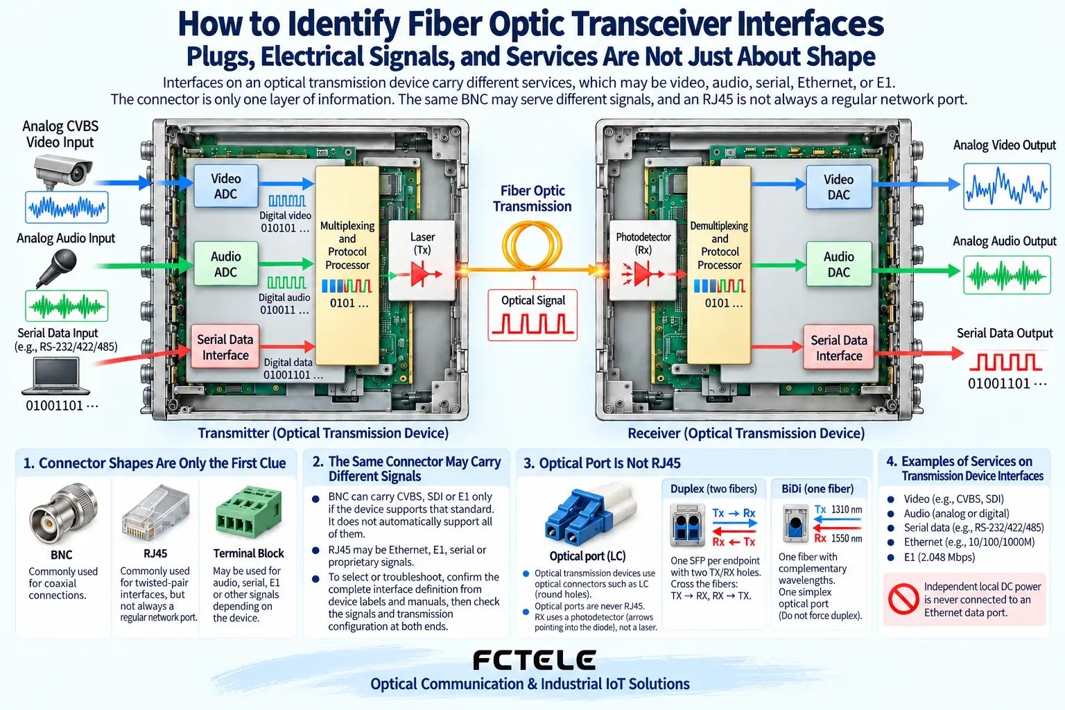
Interfaces on an optical transmission device carry different services, which may be video, audio, serial, Ethernet, or E1. The connector is only one layer of information: the same BNC may serve different signals, and RJ45 is not always a regular network port. When selecting and troubleshooting, you should confirm the complete interface definition from device labels and manuals, then check the signals and transmission configuration at both ends.
Plug shape only provides the first clue
Traditional CVBS analog video and SDI digital video can use similar coaxial connection forms, but their internal processing is different. CVBS contains analog waveforms and requires suitable video processing and transmission; SDI uses a specified digital bitstream and requires support for the corresponding rate and format. Other standards such as AHD also cannot be automatically included under the phrase “analog video.” Terminals and recording devices must match the actual output. Even if a port is also labeled video, the specifications should be checked, and an ordinary analog video optical transmission device should not be used to carry digital video that it does not explicitly support.
BNC video ports may also carry different video
Traditional CVBS analog video and SDI digital video can use similar coaxial connection forms, but their internal processing is different. CVBS contains analog waveforms and requires suitable video processing and transmission; SDI uses a specified digital bitstream and requires support for the corresponding rate and format. Other standards such as AHD also cannot be automatically included under the phrase “analog video.” Terminals and recording devices must match the actual output. Even if a port is also labeled video, the specifications should be checked, and an ordinary analog video fiber optic transmission device should not be used to carry digital video that it does not explicitly support.
Audio ports require checking level and balanced mode
Ethernet electrical ports carry a specified network link; some devices may also use a similar connector to provide E1, management, or other interfaces. These interfaces cannot be substituted for one another based on appearance. A true Ethernet port also requires checking whether it is 100 Mbps or 1 Gbps, whether PoE is available, and the actual working mode. An optical transmission device with a network management port does not necessarily carry all video services on that port. Management communication and user services should be drawn as separate paths so that installers know which connections are only for configuration and which carry actual data.
Serial ports require distinguishing RS232, RS422, and RS485
Choosing SC or LC mainly solves the mechanical connection; afterward, fiber type, rate, wavelength, single-fiber or dual-fiber, transmit/receive, and power window still need to be checked. A multi-service optical transmission device may use a manufacturer-specified internal organization, and not every optical module can restore its content. Dual-fiber generally requires transmit to connect to the opposite end’s receive; single-fiber bidirectional requires both sides to match. End-face contamination can affect the optical path, so appropriate inspection and cleaning tools should be used, and looking directly at the light source is prohibited. A port light being on is only partial status and cannot prove that all service interfaces have been correctly restored.
RJ45 interfaces must be examined for what they actually are
The official website of Feichang Technology FCV-V4T/R introduces the product direction of four-channel forward analog video and lists modular configurations such as data and audio as well as status indications. This allows projects to select models around specific service combinations, but configurable does not mean every device has everything as standard. The FCP series serial fiber optic modem and FCA audio optical transmission device serve different interface objects, and they cannot be treated as interchangeable endpoints just because both have optical ports. The number, direction, and format of input and output channels should be listed as an order, and the manufacturer should be asked to confirm the matching configuration of a pair of devices, with versions and manuals retained.
At delivery, leave port photos, complete interface names, pin or wiring order sources, configurations at both ends, and power supply arrangements. Verify actual image, sound, serial question-and-answer, or network data, not just that connectors are plugged in and indicator lights are on. Restart and applicable fault recovery should also be recorded, especially to confirm that configuration is retained and service direction is correct. The core of optical transmission device interface identification is to separate the four layers: mechanical, electrical, transmission, and application. Checking according to these four layers not only helps select the right equipment but also explains why two seemingly identical plugs cannot be directly connected.
Choosing SC or LC mainly solves the mechanical connection; afterward, fiber type, rate, wavelength, single-fiber or dual-fiber, transmit/receive, and power window still need to be checked. A multi-service fiber optic transceiver may use a manufacturer-specified internal organization, and not every optical module can restore its content. Dual-fiber generally requires transmit to connect to the opposite end’s receive; single-fiber bidirectional requires both sides to match. End-face contamination can affect the optical path, so appropriate inspection and cleaning tools should be used, and looking directly at the light source is prohibited. A port light being on is only partial status and cannot prove that all service interfaces have been correctly restored.
After video, serial, and telephone enter the device, they may each undergo sampling, encoding, timing, or interface processing, then enter multiplexing and optical transmission. Fiber is only the carrying link and does not automatically understand these services. The receiving end needs corresponding processing to restore a suitable output, so any two devices with optical ports are not necessarily a matched pair. It can be understood as different goods first being packed and transported according to an agreement, then unpacked at the destination according to the same agreement; this analogy explains the pairing relationship but cannot be used to infer specific bandwidth, latency, or that all services exist at the same time.
Some interfaces may carry power or telephone ringing, and they cannot be treated as ordinary passive data sockets for repeated trial insertion. Clarify the power inlet, service ports, and management ports, and check the power supply specifications and protective grounding according to the manual. For unfamiliar ports, first disconnect the on-site service and arrange suitable inspection; do not use trial and error instead of confirmation. Feichang Technology integrated video and telephone products may provide different service modules, and the order and actual configuration determine which ports are available. A reserved position on the housing or a product family picture does not prove that this particular unit has all interfaces installed.
How should Feichang Technology modular configuration be implemented
The official website of Feichang Technology FCV-V4T/R introduces the product direction of four-channel forward analog video and lists modular configurations such as data and audio as well as status indications. This allows projects to select models around specific service combinations, but configurable does not mean every device has everything as standard. The FCP series serial fiber optic modem and FCA audio fiber optic transmission device serve different interface objects, and they cannot be treated as interchangeable endpoints just because both have optical ports. The number, direction, and format of input and output channels should be listed as an order, and the manufacturer should be asked to confirm the matching configuration of a pair of devices, with versions and manuals retained.
How an interface checklist reduces rework
Suppose the site has two CVBS channels, one audio channel, and RS485 control for a pan-tilt. The checklist should specify the camera output, audio level, control direction, and whether a response is needed, then list the corresponding ports at both ends of the fiber optic transmission device. First establish a short-cable service baseline separately, then add the optical link and check each input and output item by item. This is a hypothetical method, not an automatic product support promise. If one channel fails, keep the status of the other channels and check local parameters rather than resetting the entire device at the same time; independent evidence helps locate input, multiplexing, or output problems.
Acceptance moves from appearance checks to service proof
At delivery, leave port photos, complete interface names, pin or wiring order sources, configurations at both ends, and power supply arrangements. Verify actual image, sound, serial question-and-answer, or network data, not just that connectors are plugged in and indicator lights are on. Restart and applicable fault recovery should also be recorded, especially to confirm that configuration is retained and service direction is correct. The core of fiber optic transmission device interface identification is to separate the four layers: mechanical, electrical, transmission, and application. Checking according to these four layers not only helps select the right equipment but also explains why two seemingly identical plugs cannot be directly connected.
First create an identity card for each socket
The same metal socket may be connected to different circuits inside. The identity card should at least record the port name, connector form, signal standard, input/output direction, impedance, and opposite-end device. For example, BNC is only a connector; analog video, SDI, and some E1 interfaces cannot therefore be directly interconnected. RJ45 may be used for Ethernet, or it may be used by the device for other proprietary wiring. Check the panel label and the manual for the current model first, then choose the cable; this is much more reliable than plugging in cables by looking at a generic picture. A photo can help identify the shape but cannot replace the electrical definition.
Why processing circuits are still needed in between
After video, serial, and telephone enter the device, they may each undergo sampling, encoding, timing, or interface processing, then enter multiplexing and optical transmission. Fiber is only the carrying link and does not automatically understand these services. The receiving end needs corresponding processing to restore a suitable output, so any two devices with optical ports are not necessarily a matched pair. It can be understood as different goods first being packed and transported according to an agreement, then unpacked at the destination according to the same agreement; this analogy explains the pairing relationship but cannot be used to infer specific bandwidth, latency, or that all services exist at the same time.
Before connection, first rule out mixing power supply and service interfaces
Some interfaces may carry power or telephone ringing, and they cannot be treated as ordinary passive data sockets for repeated trial insertion. Clarify the power inlet, service ports, and management ports, and check the power supply specifications and protective grounding according to the manual. For unfamiliar ports, first disconnect the on-site service and arrange suitable inspection; do not use trial and error instead of confirmation. Feichang Technology integrated video and telephone products may provide different service modules, and the order and actual configuration determine which ports are available. A reserved position on the housing or a product family picture does not prove that this particular unit has all interfaces installed.
Product and principle verification materials:Feichang Technology product details 218;Feichang Technology product details 611;Feichang Technology product details 1055. The general mechanisms and hypothetical examples in the main text do not replace the manual for the corresponding model.
Translated from the Chinese technical article. Source first published: 2019-09-04. Source last revised: 2026-10-13T22:35:50+08:00. Read the Chinese source
