


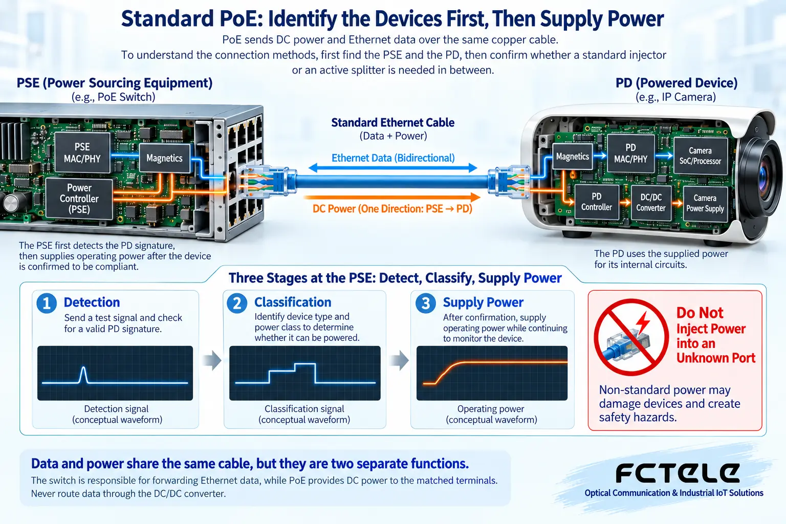
PoE lets Ethernet copper cables carry DC power to matched terminals while also transmitting data. To understand the connection methods, first find the power sourcing equipment (PSE) and the powered device (PD), then confirm whether a standard injector or an active splitter is needed in between. You cannot simplify an active device into a single forked cable, and you must never force power into an unknown network port just because the connector looks the same.
Data and power share the cable, but they are two separate functions
The switch is responsible for forwarding Ethernet data, while the PoE power supply circuit is responsible for confirming power receiving conditions and managing power. After the terminal receives power, it uses its own power receiving and power conversion circuits to supply its internal components, while data is handed to the network interface. The two paths can travel along the same network cable, but inside the device each has its own suitable processing circuit.
One of the meanings of standard PoE is that the power sourcing equipment first performs suitable powered device detection and classification before switching on the main power supply, confirming that the other end meets the conditions. This process cannot be described as if all devices with an RJ45 connector can accept the same kind of power. If a product uses passive power or a non-standard method, it may lack these protection steps, and it needs to be clearly identified and should not be mixed up with standard PoE.
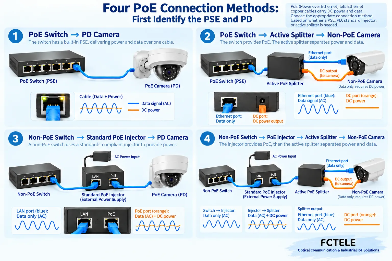
First method: A PoE switch connects directly to a PoE terminal
This is the easiest combination to understand. The switch port has suitable PSE power sourcing capability, the camera or wireless access point has corresponding PD power receiving capability, and the two are connected through a compliant network cable. Data is transmitted in both directions, power is mainly sent from the power sourcing end to the powered end, and the terminal does not need a separate local power cable.
However, “the switch supports PoE” still requires further confirmation of which standards the specific ports support, the available power, and the overall power budget of the device. For equipment where only some ports support PoE, you cannot treat any port as a power sourcing port. The maximum demand marked on the terminal should also be checked together with actual operating conditions such as startup, fill light, and heating. Being able to power on during the day is not sufficient evidence that it will work stably at night.
Second method: A PoE switch connects to a non-PoE terminal through a splitter
A non-PoE terminal only has an ordinary network port and a separate power interface, and cannot directly obtain suitable power from the network cable. In this case, you can evaluate a standard active PoE splitter: on the cable side it acts as a powered device receiving PoE, and after suitable power conversion it outputs network data and DC power separately to the terminal.
The splitter’s output voltage, polarity, connector, and current capability must meet the terminal’s requirements. A passive adapter that merely separates the wire cores is not the same as an active splitter that performs powered device detection and power conversion. You cannot assume it can be used with any camera just because there is a round-barrel power plug after splitting. The device’s label, manual, and power requirements should be checked item by item.
Third method: An ordinary switch plus a standard injector
If you already have an ordinary switch but the terminal supports PoE, you can add a standard PoE injector into the data link. The ordinary switch provides data to the injector, the injector also needs a suitable independent power supply, and it takes on the PSE’s detection and power sourcing responsibilities, then connects to the PoE terminal through a network cable.
An injector does not magically obtain a large amount of power from the data, and not every small box with two RJ45 ports is a standard PSE. You should distinguish the data input from the data-plus-power output, and check the power standard, input power, link speed, and operating environment. When higher power is needed, the power sourcing end, powered end, and cable must all meet the corresponding conditions at the same time; you cannot just swap in a higher-power adapter.
Fourth method: An injector works together with an active splitter
When neither the ordinary switch nor the non-PoE terminal has PoE capability, you can evaluate the combination of “standard injector — copper cable — active splitter.” The former sends power and data into a suitable link, and the latter acts as a powered device to receive and convert them, then connects separately to the terminal’s network port and power port. The devices at both ends are not redundant parts; they take on different power supply roles.
This type of solution adds power and conversion stages, so reliability cannot be judged simply by the fact that one power cable is reduced. You need to check the matching of standards at both ends, the splitter’s efficiency and output capability, installation space, and heat dissipation. Passing a short desktop cable test still requires verifying the actual cable length, ambient temperature, and terminal peak operating conditions, to avoid directly extending success under experimental conditions to every site.
Why the power budget should be calculated in three layers
The first layer is the power allowed to be provided by a single port, the second layer is the total budget that the switch or injector can continuously provide, and the third layer is the power the terminal actually receives after deducting cable and conversion losses. Even if multiple terminals are each below the single-port limit, their total may still exceed the overall device budget. The handling order or priority when power is insufficient depends on the product, and you cannot assume that all ports will still remain normal.
Network cable conductors have resistance, and transmitting current causes voltage drop and heat. Conditions such as cable length, conductor quality, connection points, and temperature all affect the result. Therefore, higher-power projects must check the corresponding cabling specifications and cable capability; you cannot just look at whether “all eight wires are conducting.” The common 100-meter Ethernet channel is also not a distance guaranteed with any poor-quality cable in any environment.
Standard versions must not be confused either. The common 802.3af, 802.3at, and 802.3bt have different power levels and applicable conditions, and 802.3at should not be broadly written as four-pair power. Specific capabilities such as four-pair power should be confirmed according to the corresponding standard and device implementation. This article does not provide wiring methods for forcibly injecting power into pins; installation must follow the instructions of qualified products.
Fiber uplinks and PoE power supply should be viewed separately
Feichang Technology industrial switches include product forms such as fiber uplinks and optional PoE. Fiber ports are suitable for carrying data uplinks, while PoE on the copper port side is responsible for supplying power to matched terminals. During selection, you should confirm the specific port configuration and power budget, rather than assuming that all copper ports supply power just because it is an industrial switch.
When a remote switch is connected to the control room through ordinary fiber, the site still needs a suitable power supply. Fiber will not carry the PoE current from the control room switch to the site. If a longer power supply path is needed, it should be evaluated as an independent power supply project or a verified dedicated solution; you cannot use a single fiber in a diagram to simultaneously carry ordinary PoE power transmission.
Accept according to normal operating conditions and peak operating conditions separately
First confirm the device label and wiring roles, then check the applicable detection, power receiving, and port status. After normal operation, test the terminal startup, fill light, heating, or other maximum demand scenarios, and observe whether it repeatedly restarts, drops the link, or triggers a power supply alarm. Do not use forced power supply that bypasses detection to cover up a fault, and unknown powered devices should not be used to test power.
Keep records of the injector and splitter model, output specifications, cable length, terminal requirements, and measured status. When an abnormality occurs, check data and power separately. A normal data connection does not prove that power is sufficient, and a lit power indicator does not prove that the network configuration is correct. The four connection methods ultimately all revolve around the same principle: the power supply role is clear, the power receiving specifications match, and the line and budget have been verified.
Reference materials:Microchip powered device detection;Feichang Technology optional PoE industrial switches. The principle diagrams are used to explain general mechanisms and are not measured diagrams or wiring diagrams for specific models.
Translated from the Chinese technical article. Source first published: 2019-12-18. Source last revised: 2026-10-13T20:43:40+08:00. Read the Chinese source
