


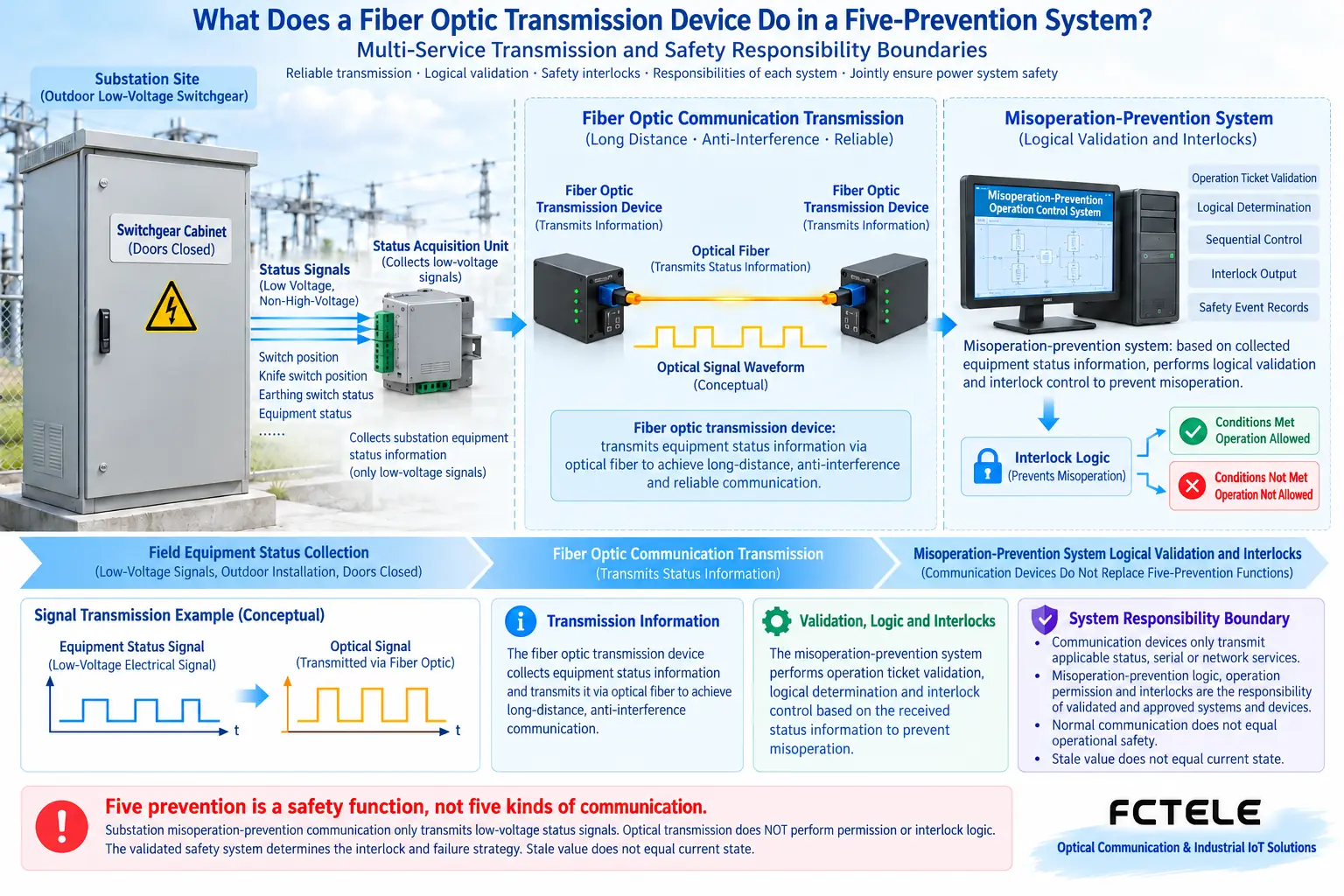
In a five-prevention system, the fiber optic transmission device is mainly responsible for transmitting applicable status, serial, or network services to the other end. The misoperation-prevention logic, operation permission, and interlock actions are the responsibility of reviewed and approved systems and devices. Normal communication does not equal operational safety. This article explains the division of communication responsibilities and does not provide methods for high-voltage switching operations or for releasing interlocks.
1. Five prevention is a safety function, not five kinds of communication interfaces
Five prevention usually refers to preventing five types of misoperation of electrical equipment, including mistakenly opening or closing a circuit breaker, operating a disconnector under load, grounding while energized, energizing while in a grounded state, and mistakenly entering an energized compartment. What is briefly described here is the concept, not the on-site operating sequence. Specific equipment and engineering requirements should be reviewed by professionals according to applicable standards.
An integrated system can combine monitoring and misoperation-prevention information processing, but this does not mean that installing just one fiber optic transmission device provides complete five prevention. On-site status collection, logic judgment, interlock execution, permissions, and management systems each have their own responsibilities. Communication equipment is only the information path among them.
An analogy for beginners is that communication equipment is like the line that delivers a report, and the misoperation-prevention system is like a professional system that executes rules based on real conditions. The report being delivered does not prove that the report content is always fresh, nor does it prove that the execution logic meets safety requirements. This difference must run through selection and acceptance.
2. What information may pass through the fiber optic transmission device
On-site status can be transmitted through applicable digital input interfaces, serial interfaces, or Ethernet services. Digital inputs express discrete states, serial ports transmit corresponding bytes and protocol messages, and Ethernet transmits network services. The electrical requirements and interpretation methods of the three types of interfaces are different, and they cannot be directly interchanged just because they share an optical path.
The sending end processes local services according to configuration and sends the corresponding data into the optical link, and the receiving end restores it to the specified channel. A fiber optic transmission device is usually not responsible for understanding the engineering meaning of each byte, nor can it judge by itself whether a certain operation satisfies the five-prevention conditions. These judgments depend on a clear system design.
The input and output definitions of communication equipment should be consistent with the on-site low-voltage interface documentation. This article does not provide high-voltage primary circuit wiring, nor does it suggest that readers connect energized equipment themselves. The design, wiring, testing, and changes involving on-site safety signals should be carried out by personnel with the appropriate qualifications.
3. How to understand multi-service multiplexing and physical isolation
Multiplexing means arranging different services in a common optical link according to the equipment design and maintaining correct attribution at the other end. It can reduce the need to lay separate lines, but sharing an optical fiber does not mean that services are mixed together, and it certainly does not mean that an optical path fault will affect only one of the services.
Some dedicated products clearly provide independent channels or physical isolation structures, and this needs to be understood based on their internal channel design and verification materials. VLANs on ordinary switches are logical divisions, and changing only one setting cannot claim to obtain completely equivalent physical isolation capability.
Isolation also does not automatically equal functional safety certification. How circuit channels are separated, how faults propagate, and how outputs behave after power loss or fiber breakage all require corresponding materials and system evaluation. “Industrial-grade,” “dedicated,” or “lightning protection” cannot be used as proof that the device can undertake misoperation-prevention logic.
4. Why the freshness of status matters
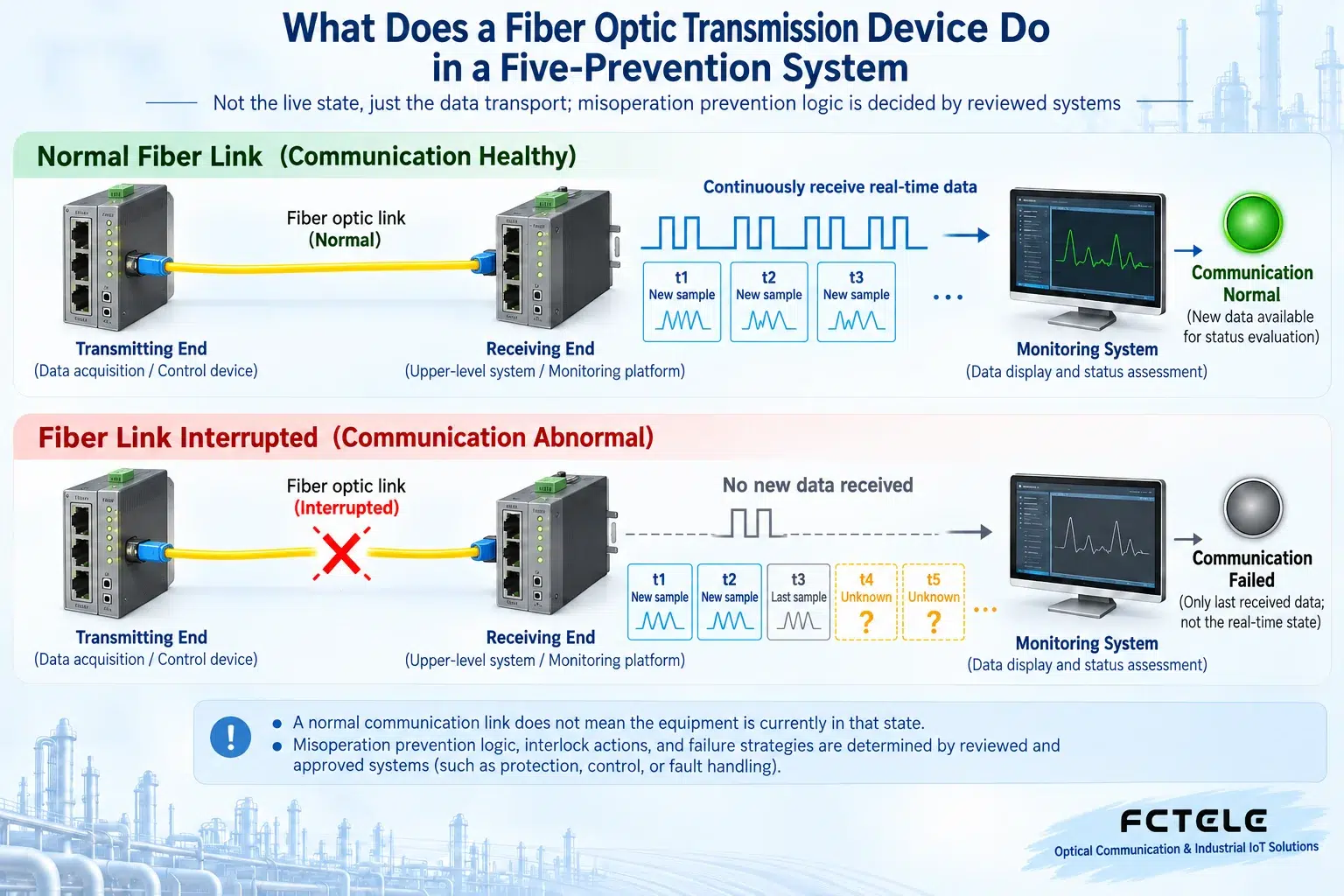
The control interface displaying a certain switch status does not prove that this is the current on-site status. After communication interruption, device power loss, or collection abnormality, the interface may temporarily retain the last data. If there are no time and quality flags, old values can easily be mistaken for real-time information.
It can be understood with a timeline: under normal conditions, the system continuously obtains new samples; after a fiber break, the last sample is no longer updated. Even if the text on the screen still shows the original value, failure should be identified by combining validity, communication alarms, and update conditions. “No change” cannot be interpreted as meaning that there is definitely no change on site.
How the system handles information failure should be determined by the reviewed and approved safety strategy. This article does not specify general permission or interlock actions, and it does not suggest restoring operations by canceling alarms, forcing old values, or bypassing interlocks. Communication troubleshooting and safety operations must be carried out within their respective authorized scopes.
5. What conditions should be verified for corresponding Feichang products
For example, the Feichang FCP-F4pD8 product details list four independent 100 Mbps Ethernet channels, as well as digital input or RS232/422/485 interfaces provided according to configuration. Multiple services sharing an optical link while maintaining corresponding channel attribution can help organize different communication needs; this is only the communication capability of this model and cannot be used to determine that the entire system already meets all five-prevention requirements.
The procurement list should separately specify the number of interfaces, electrical definitions, data direction, channel correspondence, isolation structure, and optional contents. Nominal bandwidth cannot replace the actual load assessment of each service; features supported by one configuration cannot be assumed to be present in all products of the same series.
It should also require clear status and recovery methods after power interruption, fiber breakage, and single-end abnormality. When the materials do not explain this, it is necessary to confirm with the manufacturer and have the system designer evaluate it. Absolute conclusions such as “automatic safety after fiber breakage” or “operation allowed once communication is restored” must not be added on one’s own.
6. Acceptance should distinguish communication from system safety
Communication acceptance can check whether each configured channel is transmitted to the correct endpoint, and whether there are incorrect correspondences, abnormal losses, or recovery problems. Relevant tests should be conducted in an approved environment and plan, and in-service high-voltage equipment must not be operated without authorization just to verify communication.
System safety acceptance involves the actual misoperation-prevention logic, status quality, interlock devices, and management requirements, and should be completed by the professional team responsible for that system according to the applicable plan. Test records of communication equipment can provide evidence, but they cannot replace this part of acceptance or the corresponding safety responsibility.
For example, when a group of statuses is sent to a monitoring platform through a fiber optic transmission device, the log should record not only “data received” but also the channel source, the method for identifying update time, and communication abnormality prompts. Only by clearly writing out the division between transmission and judgment can one avoid mistaking a reliable information transmission device for a complete safety control system.
Verification materials:Provisions on the Management of Misoperation-Prevention Devices (historical definition material);Feichang multi-service dedicated fiber optic transmission device. The principle diagram is used to explain general mechanisms and is not a measured diagram or a wiring diagram for a specific model.
Translated from the Chinese technical article. Source first published: 2020-05-12. Source last revised: 2026-10-13T20:43:40+08:00. Read the Chinese source
