


RS485 fiber optic modems send suitable serial electrical signals into optical fiber and then restore them at the other end. The so-called data forward and reverse directions are often defined relative to the main business or product agreement, and are not equal to A/B polarity, nor to the transmit wavelength of the optical module. When selecting a model, you must specify who initiates the request, who answers, and whether they send at the same time; you cannot just ask for a pair of 485 fiber optic modems.
RS485 describes electrical conditions, not data meaning
RS485 expresses data through differential signals, and the receiving end focuses on the difference between the wire pair. It itself does not specify instrument addresses, function codes, or temperature units; Modbus RTU is just one application that may run on it. Two devices may both have 485 ports but use completely different protocols. This article discusses optical transmission for suitable serial channels and does not assume that any byte has automatic translation capability. Installation also requires checking the serial rate, data bits, parity, stop bits, and terminal definitions, rather than guessing the wiring just from the interface letters.
Why can’t everyone send at the same time in two-wire half-duplex?
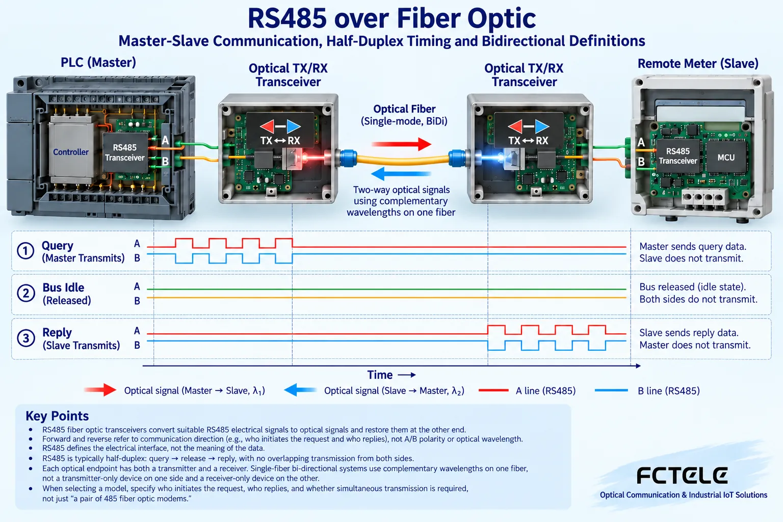
A typical two-wire half-duplex connection lets both directions share the same pair of signal wires, and different nodes should take turns occupying it according to application rules. When the master sends a request, other nodes usually receive; the requested device responds under specified conditions. If multiple nodes drive at the same time, signals may conflict and the received result is no longer reliable. It is like two parties taking turns speaking, but this analogy cannot be used to derive precise waiting times. Master-slave polling, response delays, and broadcast behavior all depend on the application, and the number of devices cannot be arbitrarily increased based only on a general theoretical maximum.
Optical transmission does not cancel the bus rules at both ends
After the electrical receiving circuit obtains the serial signal, it goes through internal device processing into optical transmission; after restoration at the far end, it drives the local RS485 line. Even if the optical path supports both directions, the copper wires on both sides must still work according to their respective bus conditions. Half-duplex automatic direction must enable and release the driver at the appropriate time; incorrect timing may truncate the first and last bytes. A fiber span can avoid forming the same copper path, but it cannot automatically correct termination, bias, or device address errors, nor does it suddenly turn a half-duplex device into a full-duplex device that can send simultaneously.
Forward and reverse are usually relative to what?
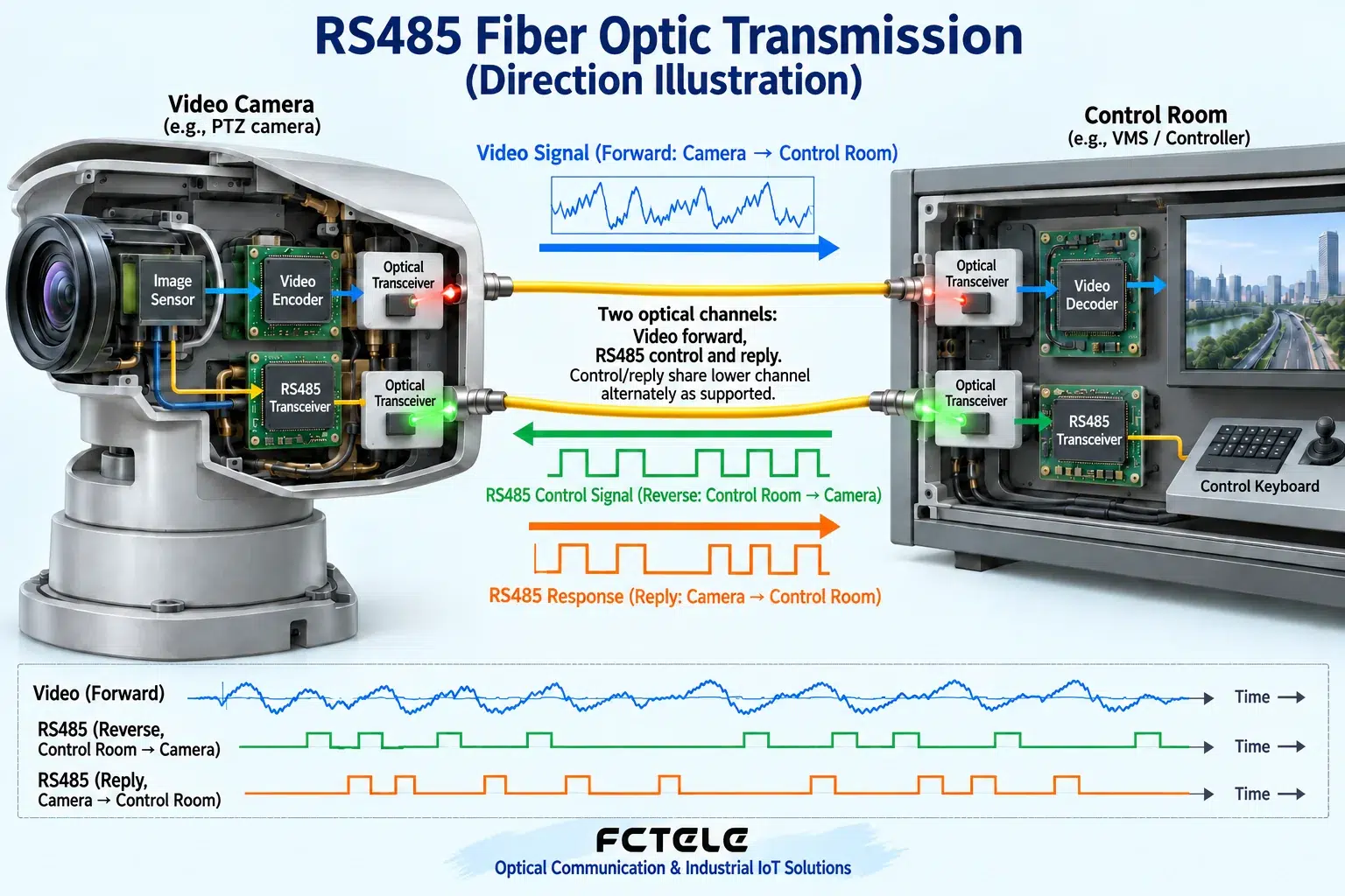
In analog surveillance systems, video is generally sent from the camera location to the control room, which is often called forward; serial control sent from the control room to the pan-tilt may be called reverse data. If the far end also needs status responses, the channel requirements change again. Instrument systems do not have the same video reference and may use other definitions. Therefore, the order must state the source and destination devices, inputs and outputs, and response requirements; you cannot just check forward or reverse. The direction markings in the manufacturer’s manual should correspond to the site connection diagram, and experience should not replace confirmation.
A, B and TX, RX cannot be confused
A and B are certain electrical terminal markings; different manufacturers may use different names, so you should check the corresponding documentation. TX and RX indicate transmit and receive functions; a dual-fiber optical path should connect one end’s transmit to the other end’s receive. Single-fiber bidirectional also requires matching complementary wavelengths and other conditions. Data forward/reverse, wire pair polarity, and optical path direction belong to different layers. When you see no communication, do not swap all cables at once and try your luck. Save the original wiring and build a known-good baseline layer by layer with short cables and the optical path, so you can see where the error actually occurs.
How does the local copper wire handle reflections and branches?
The two ends of the fiber each restore a new local electrical segment, and the cables, branches, termination, and bias should be checked separately. Termination is used to match transmission line conditions; not every device should have a fixed resistor added. Long branches and unsuitable topologies may cause reflections, and the effect becomes more obvious as the rate increases. Reference connections, isolation, and protection must also be handled according to the actual system; you cannot omit all grounding considerations just because there is fiber in the middle. Work involving strong current and protective grounding should be performed by professionals according to regulations; the functional diagram in this article is not a terminal installation diagram.
How to understand Feichang Technology’s independent serial channels
Feichang Technology FCP-D8G/R8G/Q8G series serial fiber modems are listed on the official website with configurations for one to eight channels corresponding to RS232, RS422, and RS485, and they describe features such as independent channels. This helps plan multiple services separately, but actual ordering should confirm each channel’s interface, simplex/duplex, and direction configuration. You cannot say that one combination means the entire series supports all interfaces by default at the same time. Independent channels also do not mean that different application protocols can be mixed arbitrarily; the rules of the instruments and software at both ends must still match, and the specific rate and timing should be verified according to the delivered model.
Use one instrument to establish a reproducible baseline
Suppose the control room wants to read a remote electricity meter. First, under safe conditions, use a short copper wire to confirm that the master and a single meter can communicate normally, and record the actual messages and serial parameters. Then add the paired fiber optic modem and a short fiber, and check whether the request arrives and whether the response is complete. After confirming the baseline, add the original line and other meters, and observe response time and errors. The example is not an implemented case. If only the request is received but there is no response, check the remote local bus and the optical return path separately; do not immediately conclude that the optical power is insufficient.
How to check timeout together with direction control
After the request ends, driver release, remote processing, and response return all take time. If the host timeout is too short, it will misjudge; if too long, it may slow polling and hide problems. A reasonable setting should be based on the protocol and device, not uniformly increased to a very large number. Comparing the beginning and end of messages, time intervals, and checksums on both sides can distinguish delayed direction release, parameter mismatch, and no device response. A single successful reading is only one sample; whether it is stable under continuous multi-node polling still requires recording the error rate and response distribution.
Write the direction as a complete sentence at delivery
Clearly state where the master request goes from and to, who responds, which channel is used, whether it is half-duplex, and the optical and electrical port configurations at both ends. Attach the address table, parameters, cable and termination arrangements, and save the fault and recovery test results. For surveillance scenarios, list the video and pan-tilt control directions separately to avoid a single phrase “forward transmission” covering all services. Reliable application of RS485 fiber optic modems comes from consistency among the interface, optical path, and application timing. After clarifying the direction, then look at functions and distance, so you can avoid buying equipment that can transmit signals but is not suitable for the question-and-answer method.
Why check the first and last bytes too?
When transmitting in half-duplex, the driver must occupy the wire pair at the appropriate time and release it after transmission ends. If switching is too late, the receiving end may not see the beginning; if release is too late, it may affect the other party’s response. Automatic direction is a capability implemented by the device, and not all serial systems can cancel waiting times. In addition to observing whether there is an occasional response, field testing should also check the complete message and error records. Using the same set of parameters to compare between a short copper wire and the optical link can help distinguish protocol timeout, local bus problems, and transmission problems.
The same optical cable does not mean there is only one data direction
An optical cable can contain multiple fibers, and equipment may also use different wavelengths on one fiber to carry two directions. The number of physical fibers, the number of serial channels, and half-duplex timing belong to different layers. For example, bidirectional optical transmission on one fiber may still connect to a two-wire half-duplex RS485 bus at each end; two fibers do not mean the user interface must use four-wire full-duplex. When purchasing, write these three items separately, then check pairing and bus rules, to avoid inferring product service capabilities only from appearance or fiber count.
Write acceptance results as reproducible conditions
Record who sends, who responds, serial parameters, request interval, bus wiring, and fiber cable and device versions. First establish a stable baseline with one master and one terminal, then add devices according to the allowed topology, and observe whether anomalies appear with quantity, load, or a particular branch. If professional instruments are used, personnel with the proper conditions should check waveforms and complete messages, and do not randomly short terminals on site. The final result should state that the service meets requirements under these conditions, rather than using one indicator light blink to prove that all serial protocols can operate normally.
Product and principle verification materials:Feichang Technology product details 611. The general mechanisms and hypothetical examples in the main text do not replace the corresponding model manual.
Translated from the Chinese technical article. Source first published: 2020-01-03. Source last revised: 2026-10-13T22:21:36+08:00. Read the Chinese source
