


Installing an optical module is not about forcefully pushing a metal box in. The correct process includes confirming host compatibility, taking anti-static measures, inserting in the mechanical direction, cleaning connectors, and verifying receive status. Inside the module are precise electrical-to-optical conversion components. Damage to the interface, gold fingers, or fiber end face can cause intermittent problems that are hard to find. The following uses common pluggable modules as examples. For specific operations, still follow the corresponding device manual.
First, know what the box is doing inside
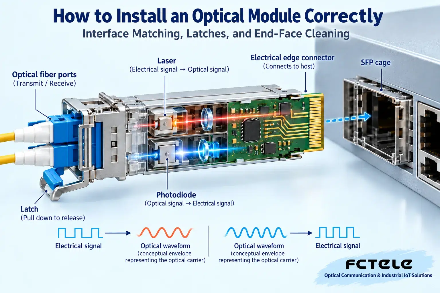
The transmit side of an optical module takes electrical data from the host and drives a laser or corresponding optical transmitter to modulate the information onto light; the receive side uses a detector to convert light into current, then after amplification and other processing sends it back to the host. The gold fingers connect power, data, and control signals. The front optical interface connects the fiber. The latch is responsible for securing the module. These are different functions. Do not treat the latch as a handle that can be pulled in any direction. Modules may look similar, but their internal rate, wavelength, encoding, and power requirements may not be the same. Understanding this path shows why, before installation, you must confirm both electrical compatibility and optical pairing, rather than only checking whether the slot can fit it.
Before installation, check the host and specifications at both ends
First check the module types, port rates, and compatibility requirements supported by the host, then compare them with the optical specifications of the module at the far end. For dual-fiber, usually check the transmit wavelength, receive capability, and fiber core type; for single-fiber bidirectional, also check the complementary relationship between the two ends. Rated transmission distance is a description of capability under certain conditions, not an on-site guarantee. Link connectors, splices, and bend losses all need to be considered. Receive power has upper and lower limits. A long-distance module may not be suitable for a very short link. Even if a module has digital diagnostic functions, it does not mean the host can definitely read all information. When purchasing and replacing, keeping compatibility tables and model labels is more reliable than identifying models only by pull-tab color.
How to do anti-static and appearance checks
Use anti-static measures in an environment that meets operating standards. Touch the metal shell of the module rather than casually touching the gold fingers. Check the housing, latch, and contact pads for deformation, dirt, or damage. Do not use ordinary erasers, metal tools, or unknown cleaners on precision contacts. Dust caps can reduce exposure, but they do not guarantee the end face is absolutely clean. A module just removed from equipment may be hot. During operation, pay attention to the temperature and waiting requirements in the manual. If anything abnormal is found, stop installation and record photos; forced insertion may damage both the module and the host slot, turning a small problem into hardware failure at both ends. Normal appearance also cannot replace subsequent functional checks.
During insertion, let the guide rail and latch do the work
Confirm the direction of the module and slot, insert smoothly along the guide, and do not pry sideways. Different latch structures may have different opening and closing steps. Follow the installation requirements for that structure. After reaching the locked position, gently confirm according to the manual whether it is fixed. Do not use strong pulling to verify. If you clearly meet resistance, withdraw and check the direction, guide rail, and latch, rather than continuing to use force. Whether hot plugging is allowed depends on the module and host design and on-site maintenance rules. “Pluggable” is not authorization to hot-swap freely in all situations. When installation is temporarily not connected to a patch cord, keep dust protection in place to avoid leaving the optical port exposed to cabinet dust for a long time.

Why can a small speck of dust cause big trouble?
The connector end face aligns a very thin fiber core. Light needs to couple stably from one end to the other. Dust, oil, or scratches can block, scatter, or reflect part of the light, weakening the received signal and, in severe cases, causing bit errors. An end face that looks clean to the naked eye may still have contamination that affects transmission, so appropriate end-face inspection tools are more reliable than impressions. Use specified cleaning tools and follow the process of inspect, clean, and inspect again to avoid inserting a dirty connector into a clean module and contaminating both. Do not look directly at the optical port or fiber core. Communication light is often invisible. Not seeing a bright light does not mean there is no danger. The illustrated light beam only explains the coupling mechanism; it is not a phenomenon that can be confirmed with the naked eye.
Correct order for connecting and removing patch cords
Confirm that the connector type and end-face form match. Insert along the interface direction until locked. Do not casually mix different end-face types. For dual-fiber, connect transmit to the far-end receive. For single-fiber, match the module wavelengths. Cable arrangement should leave suitable bending space and maintenance margin. Manage the bend radius according to the fiber cable specification. Do not apply one uniform value to all patch cords. When unplugging, first release the connector lock and hold the connector body. Do not pull the fiber. When the module needs to be removed, usually first remove the fiber, then release the fixing according to the module latch structure, then take it out smoothly and put the dust cap back on. Do not forcefully pull the pull-tab while the patch cord is still dragging on the module.
After installation, how do you know it is truly normal?
Observe whether the host recognizes the module, whether the port establishes the expected link, and whether both ends report abnormalities. When digital diagnostics can be read, record transmit power, receive power, temperature, and alarms, then compare them with the thresholds for that module. Do not treat some online example power as the normal range for all modules. Check that traffic transmits in both directions, observe whether error counters increase, and test with expected packet lengths and loads. If the link light is on but packets are lost, it may also involve contamination, rate, encoding, and receive overload; if there is no link, check compatibility, direction, and configuration. Installation does not equal acceptance. Physical fixation, optical status, and actual traffic are three different checkpoints.
Maintenance records make the next time easier
Save the module model, serial information, installation port, far end, fiber cable number, and acceptance results. When replacing a faulty module, record diagnostic data before and after replacement, keeping other conditions as consistent as possible, to help determine which part the change came from. If a connector is still abnormal after cleaning, consider end-face damage or other optical path problems. Do not wipe repeatedly without limit. For devices that cannot read diagnostics, personnel with the proper conditions can also use suitable instruments to check. The ultimate goal is not to complete one insertion and removal, but to establish a stable, traceable optical link. Beginners only need to stick to “match first, install safely, verify last” to avoid the common mistakes of forced insertion, dirty insertion, and only looking at the light.
Principle verification materials:Official material 1. The general mechanisms and examples in the text do not replace the manual for the corresponding model.
Translated from the Chinese technical article. Source first published: 2021-04-30. Source last revised: 2026-10-13T20:58:17+08:00. Read the Chinese source
