


When looking at industrial switch performance specifications, you need to separate port rate, switching capacity, packet forwarding rate, and actual service throughput. Gbps describes the number of bits per second, while Mpps describes how many frames are processed per second; the numbers cannot be directly compared by size. This article explains the assumptions and limits of the calculations, and corrects the old article’s mistakes of writing packet forwarding rate as Mbps, incorrect byte conversion, and using capacity numbers to directly declare line rate.
Data passes through interfaces, chips, and egress
The terminal organizes data into Ethernet frames and sends them to the ingress, and the switch selects the egress based on the destination address and configuration. Hardware needs to receive, parse, and forward, and each egress also needs to transmit at its own rate. When multiple ingresses compete for the same egress, data may wait in queues. Being able to connect an interface only means a link is established; it does not prove that all frames can be sent out in time under sustained multi-port load.
You can understand the device as multiple ingresses sharing internal processing and different egresses, but the road analogy cannot be used to derive precise performance. Actual results depend on frame length, direction, functions, configuration, and load. When asking for a quote or looking at a test report, look at these conditions together; do not just pick out the largest value on the specification table.
First distinguish bits, bytes, and frames
Lowercase b means bit, uppercase B means byte, and usually one byte is eight bits. Mb/s or Mbps means megabits per second, and MB/s means megabytes per second. Network rates usually use decimal prefixes; software may also use different display conventions, so confirm the unit when comparing. The old article’s statement that “one MB equals 1024 bytes” is incorrect, and data volume cannot be calculated on that basis.
pps means the number of frames or packets processed per second, and Mpps is millions per second. At the same bit rate, many small frames require a higher frame processing rate; longer frames carry more data per processing event. The specific meaning of “packet” in device documentation needs to be checked, and especially do not mix interface line rate, effective service data, and processing rate into one parameter.
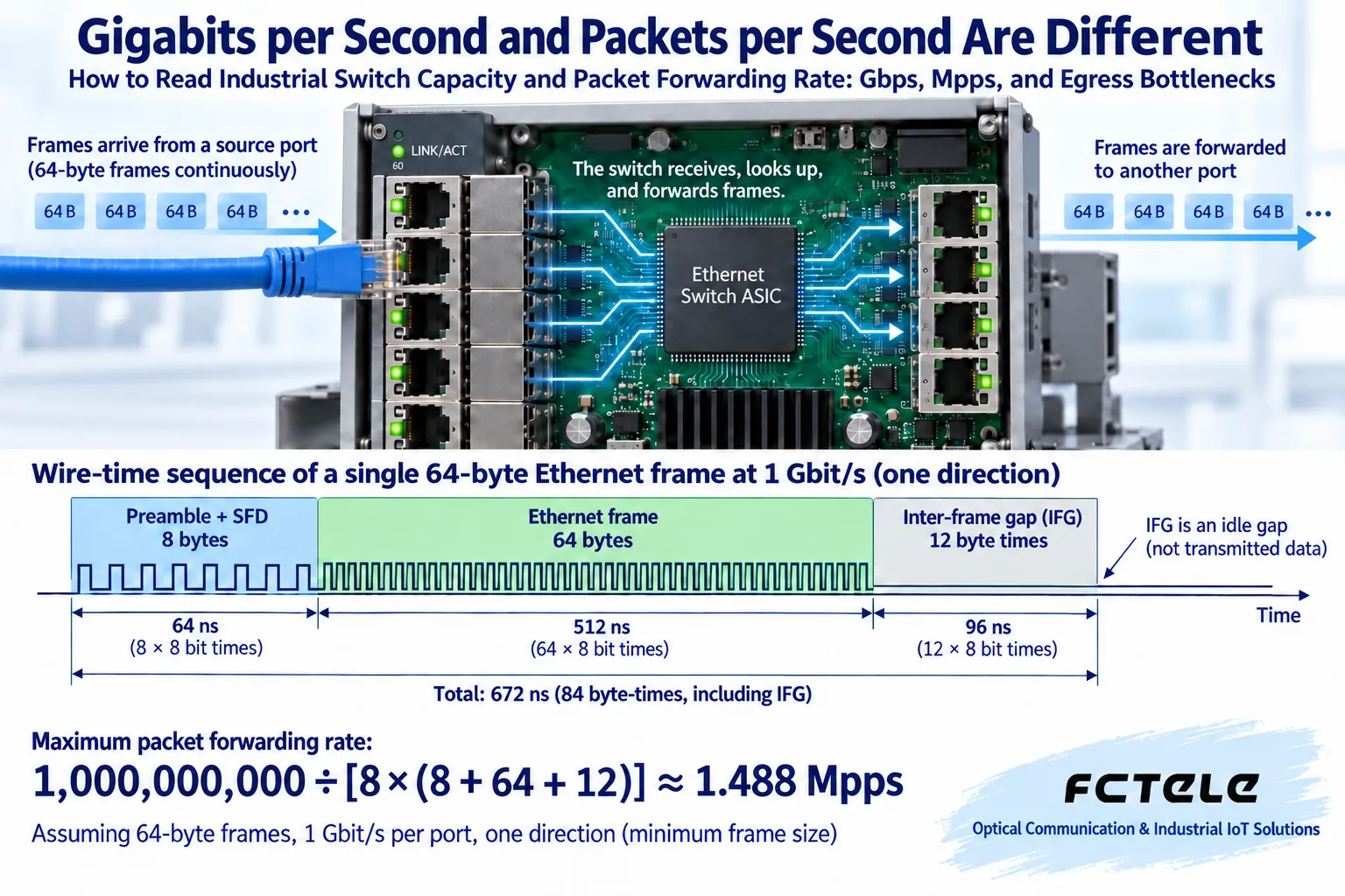
How 1.488 Mpps is obtained
Taking one Gigabit Ethernet port, one direction, and a 64-byte Ethernet frame as an example, the cable time occupancy also includes the 8-byte preamble and start frame delimiter, and the frame gap corresponding to 12 bytes of time. The frame gap is not another data field, but it occupies the transmission timing. Convert the total time occupancy into 84 bytes, then multiply by eight bits per byte, to calculate the theoretical frame rate for this example.
The calculation is 1,000,000,000 ÷ [8 × (64 + 8 + 12)], which is approximately 1,488,095 frames per second, or 1.488 Mpps. For 100 Mbps under the same convention, it is about 0.1488 Mpps, and for 10 Gigabit it is about 14.88 Mpps. This is a theoretical value under the stated conditions; it does not prove that a certain switch, any configuration, or all frame lengths achieve this performance, and the preamble must not be incorrectly written as an extra 64 bytes.
What adding port rates can show
Suppose there are 24 100 Mbps ports and two Gigabit ports. The sum of nominal one-direction rates is 4.4 Gb/s; if all ports are counted as full duplex at the same time, the common comparison convention is 8.8 Gb/s. This sum helps check the specification convention, but it cannot directly prove that the internal switching architecture, buffers, and all functions have no bottlenecks. How the manufacturer counts switching capacity needs to be confirmed in the documentation.
Similarly, adding the theoretical 64-byte frame rates in the receive direction of each port, 24 × 0.1488 + 2 × 1.488 is about 6.5472 Mpps. It should not be written as 6.6 Mbps, and it should not be arbitrarily multiplied by two without stating the convention. If a test report counts transmit, receive, or multiple chips separately, unify them before comparing. The example is not recommending a fixed 24-plus-2 configuration.
Sufficient capacity can still get stuck at one egress
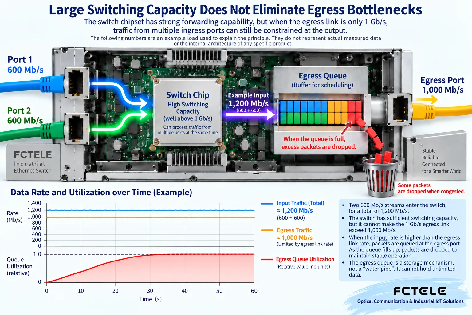
Two Gigabit ingresses each continuously send 600 Mb/s to the same Gigabit egress, for a total input of 1,200 Mb/s, but the egress can at most transmit at its own physical rate. Even if internal processing capacity still has margin, a backlog will occur; if it lasts long enough, limited buffers cannot hold all frames. The load here is an assumed value and does not represent a measurement or a guarantee for any model.
Increasing internal switching capacity will not automatically change the egress rate. You need to adjust service paths, egress capability, or load; link aggregation should also check support at both ends, member status, and traffic distribution method, and a single flow may not be able to occupy all members. Do not ignore the lower capability of server network ports, uplinks, or remote links just because the specification lists a very large switching capacity.
Line rate and no packet loss require test conditions
“Line rate” usually emphasizes that the device forwards at the interface rate under specified traffic conditions, but you should ask what frame length, ports, direction, and functions are used. Testing only two ports cannot prove that all ports work at the same time; testing only large frames cannot prove small-frame processing capability. The configuration of VLAN, routing, access rules, and other functions should be comparable to the target service.
RFC2544 provides performance test methods for network interconnection devices, including throughput, latency, and frame loss; it is not a product certification or a unified pass threshold for every project. A report obtained according to its methods should state the test configuration, load, frame length, and results. Do not perform destructive full-load tests on a live production network by yourself; it is suitable to carry out in an isolated environment by qualified personnel.
Buffers, latency, and QoS cannot be viewed apart from load
Buffers can temporarily store data that arrives too fast, but their sharing method, available amount, and queue allocation differ by implementation. A larger buffer may alleviate some bursts, but it may also increase waiting time; you cannot assume that the larger the buffer, the more real-time all services are. Device forwarding latency, queuing, link transmission, and application response are not the same metric, and the old article’s uniform 10 microsecond or 10 millisecond requirement should not be applied.
QoS can arrange priority or scheduling according to applicable rules, helping to take care of critical traffic during competition. It cannot increase total bandwidth out of thin air, nor can it guarantee that all traffic will not be lost. Overly strict configuration may restrict normal services, and it should be verified with actual applications and tests under the same conditions. The priority requirements for control, video, and backup need to be clarified by the user, rather than setting all services to the highest level.
Clarify first when product parameters are doubtful
Feichang Technology 3422 public details lists port statistics, queue management, SFP information, and configuration import/export; these capabilities can be used to observe and save configurations. Its parameter page’s “packet forwarding rate” appears with the unit Mbps, so the supplier should be asked to check the correct unit, statistical convention, and test conditions; this article does not convert that number into a proven Mpps capability.
Different models may have different optical ports, electrical ports, module combinations, and firmware. Ask the quote to state the delivered configuration and provide documentation and test evidence corresponding to that configuration; do not use a third-party device supporting a function to infer that all Feichang Technology series support it. When only basic connectivity is needed, you also do not need to pay for routing or advanced management parameters that have no business use.
Complete the selection with a reviewable record
Record terminal traffic, peaks, egresses passed through, and expansion needs, calculate each actual path first, then check ports, capacity, and frame handling. During testing, save the device version, frame length, flow direction, duration, transmit and receive increments, and application performance. Align counters to the same time range, and distinguish interface errors, queue drops, and terminal processing failures.
The procurement conclusion should be able to explain where the margin comes from, which item still needs confirmation, and why the configuration meets the service. If the bit rate is increased, terminals are added, or modules are replaced later, recalculate and test along the same path. Compared with adding parameters together and directly declaring qualification, this method makes it easier to find bottlenecks and also allows maintenance personnel to reproduce the verification process.
References:RFC2544 and RFC6815 on restrictions on using test methods on production networks; Feichang Technology details are used to check specific observation functions. The two figures are general illustrations, not measurements.
Translated from the Chinese technical article. Source first published: 2019-09-06. Source last revised: 2026-10-13T19:01:44+08:00. Read the Chinese source
