


Bandwidth management on an industrial switch is not about turning a gigabit port into an infinitely wide channel. It is about controlling, on a limited egress, who sends first, who waits, and who needs to reduce sending. First find where congestion actually occurs, then check which queues, rate limits, and multicast functions the model supports, and finally validate with real traffic. This is more reliable than turning on every “optimization feature” at once.
1. Every port is gigabit, so why is there still lag?
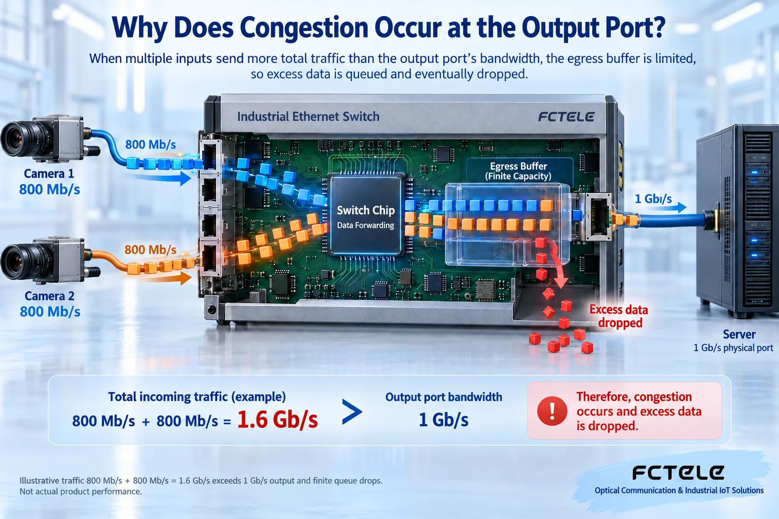
When a switch receives an Ethernet frame, which is a piece of data with addresses, it decides which port the frame should go to. Multiple ingress ports can receive at the same time, but the same physical egress must still send frames out in order in one transmit direction. You can think of it as several branch roads merging into one main road: adding more branch roads does not automatically increase the main road’s carrying capacity. This analogy only explains the merging relationship; it does not mean network data and vehicles are controlled in the same way.
Suppose two devices each send 800 megabits per second to the same server for a short time, while the egress connected to the server is only 1000 megabits per second. The instantaneous input total exceeds the egress capacity, so the extra data can only enter the buffer first. A buffer is storage space near the chip used to temporarily hold frames, and its capacity is limited. If data keeps entering faster than it leaves, the queue grows longer and longer, and eventually frames may be dropped. The numbers here are a teaching example, not measured performance of any specific device.
A low one-minute average utilization does not mean there is no congestion. Camera keyframes, file uploads, and many devices reporting at the same time can create bursts within a very short period. Average statistics smooth out these peaks, just as a road can have a low daily average and still have long lines during morning rush hour. Therefore, observe egress utilization, drop counters, queue status, and service latency together, not just total traffic.
2. What exactly does QoS change?
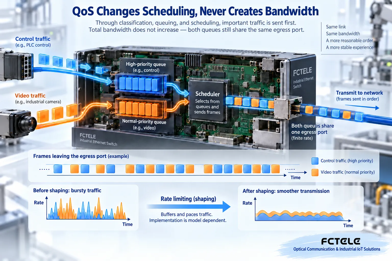
QoS is usually translated as quality of service. On a switch, frames can first be classified by port, priority in the frame, or other supported conditions, then placed into different queues, and finally the scheduling policy decides the transmission order. It mainly solves the problem of how services share opportunities when congestion occurs. It does not create physical bandwidth out of nothing, and it cannot repair damaged cables or receive errors.
For example, control commands are sensitive to waiting time, while historical file uploads can be slower. A reasonable policy can let control traffic get transmission opportunities faster and let file traffic use the remaining resources. But you cannot mark every frame as the highest priority: if everyone is “priority,” classification loses meaning; if high priority occupies the egress for a long time, low-priority services may also go without service for a long time. The policy should be designed with the strict priority, weighted scheduling, and traffic limits supported by the device.
DSCP is a type of priority marking in IP packets, and Layer 2 Ethernet also has a corresponding priority expression. A marking is not a pass that automatically gets guaranteed treatment; the switch needs to correctly recognize it, map it to a queue, and apply the corresponding policy on the congested egress. You cannot casually trust high-priority markings that all endpoints carry by themselves. Whether the device allows a trusted boundary to be set by port should be checked in the corresponding manual.
3. Rate limiting and shaping are not the same thing
The term rate limiting may refer to different mechanisms in an interface. Traffic policing usually drops frames or remarks them when conditions are exceeded; traffic shaping keeps temporarily excessive frames in a queue and sends them at a set pace. The former may increase drops, and the latter may increase waiting. Both need to consider burst size and buffer boundaries. You cannot look at just one number and assume the effects are exactly the same.
You can first constrain non-critical large-file services and reserve reasonable headroom for control and monitoring, but do not directly copy someone else’s percentage. Port line rate, protocol overhead, endpoint peaks, and downstream link capacity are all different. Setting it too low can cause the service itself to fail, while setting it too high may not relieve congestion. When changing settings, record the original values and arrange a test window that can be restored.
4. What do VLAN, multicast, and link aggregation each solve?
VLAN is a method of logically dividing a network and can limit the scope of broadcast propagation. It cannot turn the same uplink line into several independent physical lines: if the traffic of several VLANs still converges on the same egress, they still compete for egress capacity. Before dividing, determine endpoint membership and cross-network communication needs, so that trying to “save bandwidth” does not cut off necessary services.
Video multicast may require IGMP Snooping, which means the switch observes group membership and sends traffic only to ports that actually have receivers. You also need to check the querier and topology. You cannot just turn on one switch and assume member status will always be correct. Multicast optimization reduces unnecessary copies; it is not video encoding compression, and it does not reduce the traffic on ports that must receive that video.
Link aggregation uses multiple compatible physical connections as one logical connection, usually distributing different data flows to member links according to certain rules. It helps increase the total capacity of multiple flows, but one data flow usually still lands on one member, so you cannot simply promise that a single transfer speed will double. Both ends must support it and be configured correctly; just plugging in an extra cable may form a loop instead of adding capacity.
5. How do Feichang Technology products fit into a real solution?
The industrial switch category on the Feichang Technology website includes different managed and unmanaged products, and the functions of one series cannot be generalized to all devices. The mini DIN-rail managed gigabit product with four electrical ports and two optical ports listed on the website states that it supports VLAN, IGMP Snooping, and eight queues based on DSCP. These capabilities can serve as selection clues for a mixed control and video network, but queue mapping, scheduling methods, and configurable combinations still need to be confirmed with the complete model and firmware documentation.
Eight queues do not mean eight independent gigabit channels; the product has two optical ports, but that does not mean they are aggregated by default. If shaping, application recognition, or a higher level of real-time mechanism is needed, supporting evidence should be checked separately. You cannot infer that all are present just because the documentation says QoS. Optical port distance, modules, and power options should also be confirmed separately.
6. How can a beginner verify step by step?
First draw the path of data from the endpoint to the server, and write down the port rate and service direction of each segment. Then save the original configuration and normal state, and check the negotiated rate, error counters, and cable conditions. After confirming the physical link is healthy, add real services one by one and find where drops or waiting begin to increase. One successful Ping only shows some kind of connectivity at that moment; it cannot replace peak-load verification.
Change only one type of policy at a time, and compare control service latency and variation, video continuity, file completion time, and egress drops. Observation should cover both stable periods and bursts when devices report at the same time and services recover. Record the model, firmware, topology, configuration, test method, and time range so the supplier can reproduce it. If the long-term average load already exceeds egress capacity, prioritize reducing useless traffic, adjusting services, or expanding capacity; queuing policy cannot replace capacity planning.
The dynamic bandwidth allocation, application recognition, and “ensure real-time” mentioned in the old article cannot be treated as common capabilities of all industrial switches. This article replaces these broad statements with checkable mechanisms and boundaries: first determine the bottleneck, then choose supported tools, and prove improvement with service results.
Sources:Feichang Technology industrial switch category;Four electrical and two optical managed product details;Cisco explanation of policing and shaping mechanisms. The sources are for understanding mechanisms and do not provide cross-model universal configuration commands.
Translated from the Chinese technical article. Source first published: 2024-12-03. Source last revised: 2026-10-13T19:28:50+08:00. Read the Chinese source
