


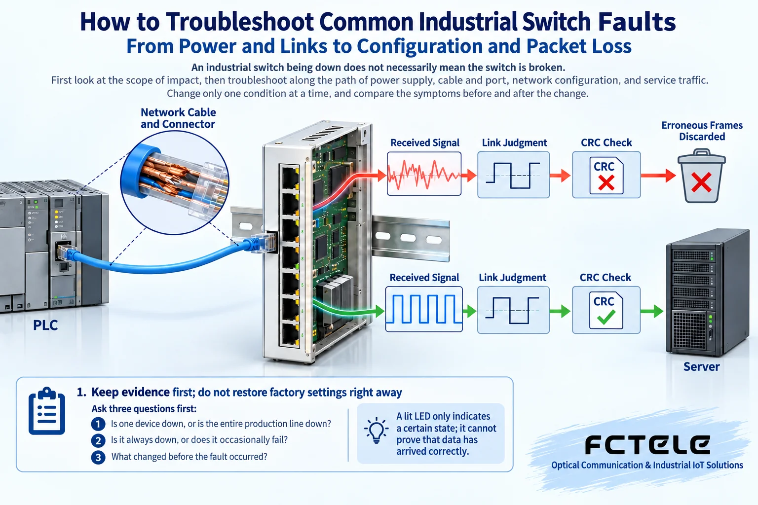
An industrial switch being down does not necessarily mean the switch is broken. First look at the scope of impact, then troubleshoot along the path of power supply, cable and port, network configuration, and service traffic. Change only one condition at a time, and compare the symptoms before and after the change. A lit LED only indicates a certain state; it cannot prove that data has arrived correctly.
1. First keep evidence; do not restore factory settings right away
Ask three questions first: Is one device down, or is the entire production line down? Is it always down, or does it occasionally lose packets? Before it happened, were the network cable, optical module, power supply, or configuration changed? Save the device model, firmware version, port number, topology, fault time, and alarm records together. Intermittent faults especially need time correspondence; otherwise, after recovery it is very difficult to determine the root cause.
When you can log in to the network management, back up the current configuration and record the port negotiated rate, duplex status, error frames, discarded frames, link up/down count, and device uptime. Look at how much the counter increases within the same observation window, not just that the cumulative value is large. If the device has just restarted, a very small counter also cannot prove that the fault does not exist. Unmanaged switches do not have these statistics; you can locate the fault by replacing items one by one with confirmed good spare parts.
In a production network, restoring factory settings, upgrading firmware, or unplugging ring network cables will change the service path. First obtain a maintenance window, save the configuration, and prepare a rollback plan. Do not directly stop all devices for troubleshooting, and do not temporarily wire between unconfirmed ports, to avoid creating a new loop.
2. The whole device does not respond: first check power supply and environment
When the power indicator is off, check the power switch, fuse, terminal tightness, and polarity, then verify the input range against the device nameplate. Measuring live terminals must be done by qualified personnel using suitable instruments; customers should not disassemble the device to measure internal circuits. A fanless DIN-rail device does not have the judgment that “if the fan stops, it is broken”; the color of the LED and the meaning of steady on should also be based on the specific manual.
If it works normally with no load but restarts after more devices are connected, check the power supply capacity, load changes, and voltage records. PoE switches also need to separately calculate the power consumption of the switch itself and the powered device load. Dual power inputs do not mean two truly independent paths: if both inputs are connected to the same upstream power source, a common failure point still exists. Verifying redundant power supply should be tested path by path during a maintenance window, not inferred from the number of terminals.
Check whether the heat dissipation space is blocked by cable bundles, whether the enclosure has water ingress or condensation, whether terminals are corroded, and whether protective grounding meets installation requirements. Industrial-grade devices also have operating temperature, humidity, and installation limits; a metal enclosure does not mean it can operate in any environment. If there is a burning smell, smoke, obvious charring, or water ingress, safely disconnect power and contact maintenance; do not repeatedly power on and try again.
3. A single port is down: separate the cable, module, and port
First use a known-good short network cable and terminal to test, then replace the original cable; if the short cable recovers but the original long cable still fails, check the wire sequence, connector, length, bending, and interference environment. A simple continuity test only shows that the conductors are connected; it does not mean high-speed transmission performance is qualified. When needed, verify with a certification tester suitable for the cable category, rather than repeatedly crimping the RJ45 plug.
For optical ports, verify the rate, single-mode or multimode, wavelength, and fiber type at both ends. For dual-fiber, the local TX should connect to the remote RX; for single-fiber BiDi, use paired modules with complementary transmit and receive wavelengths. The same fiber shape and connector do not mean the two ends are compatible. Do not look directly into the optical port; handle the end face by “inspect, special cleaning, inspect again,” and do not insert ordinary alcohol cotton balls into the device optical port.
Optical modules that support digital diagnostics can read transmit and receive optical power, but you should check the receive sensitivity, overload upper limit, and link loss against the module specifications. Both insufficient optical power and excessive optical power can cause abnormalities. When replacing modules, follow the manufacturer’s allowed insertion and removal method and electrostatic protection requirements; short-distance testing also cannot omit the overload check.
Keep the terminal, configuration, and cable unchanged, and only replace with an allowed port of the same type, then observe whether the problem follows the port. If the problem follows the cable, check the cable first; if the problem always stays with the port, also rule out port configuration before suspecting hardware. Do not directly conclude that the port is damaged after one successful replacement; contact problems and negotiation changes may also temporarily improve the symptom.
4. LED on but service not working: check configuration boundaries
Link establishment is only the first step. Being able to access the management address does not mean the service VLAN, uplink tag, or terminal address configuration is correct. Compare with a normal path and check the port enabled status, access VLAN, trunk allowed list, PVID, and terminal IP, mask, and gateway. Cross-subnet services also need routing and access policy checks; do not attribute all problems to the Layer 2 switch.
Rate and duplex are the result of negotiation between two adjacent ends. Under normal circumstances, keep auto-negotiation on both sides; when special devices require fixed parameters, match them according to both manuals, and do not fix only one side. A mismatch between half-duplex and full-duplex may cause performance abnormalities. An increase in CRC errors can indicate a physical link problem, but you should still judge together with platform documentation and other counters; do not conclude that the module is damaged based on only one indicator.
A forgotten password is different from a service forwarding fault. First confirm whether there is still an authorized management channel, handle it according to the recovery procedure for the specific model, and record whether the configuration will be cleared. Modular chassis also need checks of slots, power, compatible versions, and alarms; a normal fixed-port switch cannot use the repair conclusion that “all modules are connected to a replaceable backplane.” Leave internal faults to the manufacturer for diagnosis.
5. Intermittent packet loss: distinguish errors, congestion, and loops
When multiple cameras send data to one egress at the same time, even if the average utilization is not high, a short burst may fill the buffer. If the egress discard counter increases but CRC does not increase at the same time, check the egress bandwidth, bursts, and queues. Reduce irrelevant traffic, adjust the service path, or reasonably configure QoS, then verify critical services; QoS assigns priority and does not create additional bandwidth.
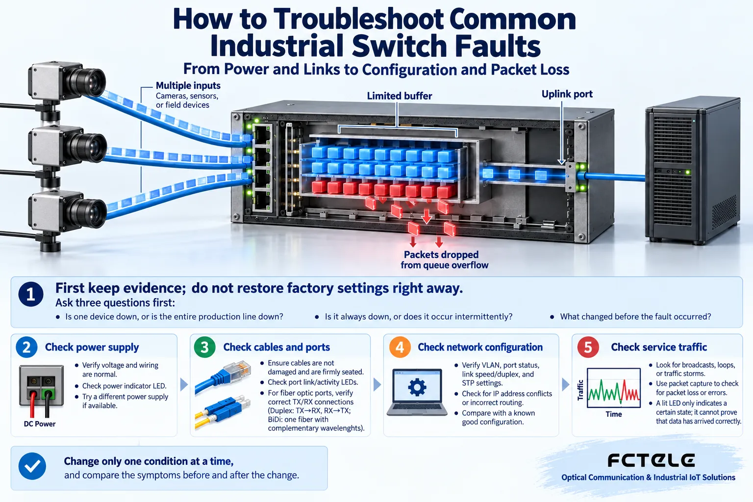
When broadcasts suddenly increase, MAC addresses repeatedly migrate, or multiple ports are congested at the same time, check for accidental loops and protection protocol status together with the topology. VLANs divide different broadcast domains, but storms can still occur within a VLAN; there is no universal threshold that “broadcast at thirty percent will necessarily cause a fault.” Do not disable STP or ERPS to eliminate alarms; first confirm whether the faulty link and protection mechanism are working as designed.
6. How to confirm after repair
After recovery, rerun the original service load and observe error frame and discard frame increments, link stability, terminal response, and alarms. The test should cover the time periods and actions that were previously prone to problems, such as centralized camera startup, device switching, or high load. One successful Ping only proves that a small number of packets went back and forth at that time; it cannot replace complete service acceptance.
Keep a record of “symptom, evidence, single change, result, rollback method.” If you suspect a firmware problem, first check the applicable hardware version and the manufacturer’s fix notes, and upgrade only after verification in a rollback-capable environment. For selection, you can view the Feichang Technology DIN-rail industrial switch category; network management, ring network, optical module diagnostics, and power supply capability need to be confirmed model by model, and the features of one device cannot be treated as common capabilities of all industrial switches.
References:Cisco port and interface troubleshooting documentation;Feichang Technology DIN-rail industrial switch category. This schematic is a generic mechanism illustration and does not represent the actual product or performance test. The effective troubleshooting content from the original 1675 and 1450, 1201, 1514, 2217, 2163, and 1187 has been organized, and unsafe or unsupported recommendations have been corrected.
Translated from the Chinese technical article. Source first published: 2020-12-31. Source last revised: 2026-10-13T19:28:50+08:00. Read the Chinese source
