


Explains the structure, power supply, and transmit-receive process of SFP optical modules and standalone Ethernet media converters, and checks combinations by service protocol, rate, fiber, and power supply.
First, look at which problem the device solves
Optical modules and fiber media converters may both use fiber, but they are not the same layer of thing. A common SFP optical module is an optical-electrical transceiver component that is inserted into a switch or another host device; a standalone Ethernet fiber media converter is usually a media conversion device with an electrical port, an optical port, and a power input. The former provides an optical interface for the host, while the latter extends an existing Ethernet electrical connection to fiber. Seeing a metal shell or the same LC socket is still not enough to judge whether the services can interoperate. Before buying, you should first draw the devices at both ends, as well as every conversion between electrical signals and optical signals in between.
This article discusses Ethernet services. Although video fiber optic transmission devices, serial fiber optic transmission devices, and PON optical network terminals also connect to fiber, their service encoding, access method, or management relationship may differ, and they cannot be connected together just because the plugs are the same. The most direct way to identify them is to check the port descriptions and product manuals: whether the host has an SFP slot, whether the existing terminal is an RJ45 Ethernet interface or another service interface, and what signal the receiving end expects to receive.
Optical modules rely on the host to work; they are not passive components
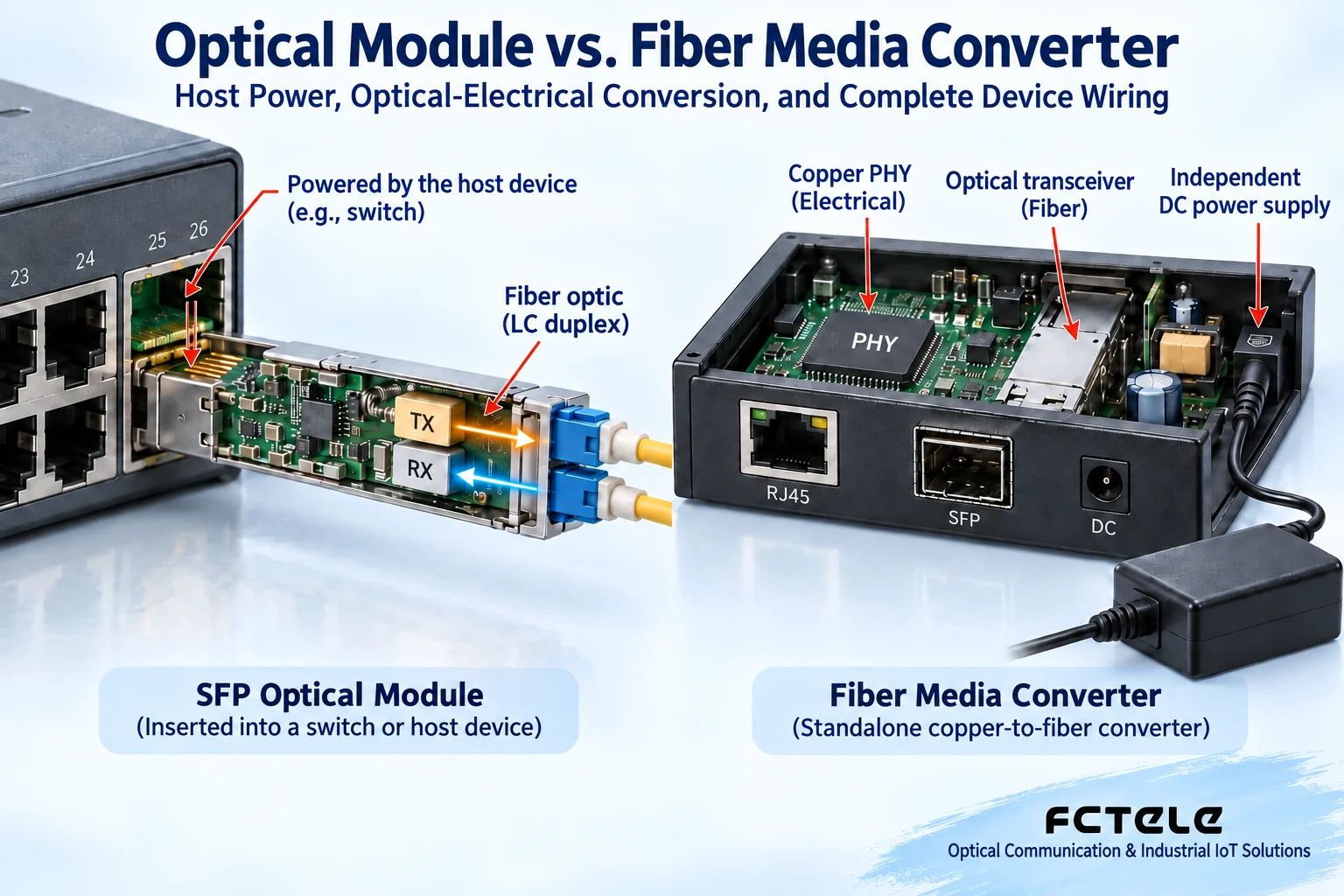
SFP is a package form of a pluggable transceiver. After the module is inserted into the host cage, it obtains power and high-speed electrical signals through the gold fingers. In the transmit direction, the driver circuit hands the electrical signal sent by the host to the laser, and the laser converts the change into a change in optical power; in the receive direction, the photodetector converts the received light into an electrical signal, which is then returned to the host through circuits such as amplification. The internal implementation used by different rates and standards differs somewhat, but these processes all require electrical energy.
Therefore, “the module has no separate power socket inside” does not mean “the module does not need power.” The host’s power supply, heat dissipation, interface standard, and module support range are all working conditions. Being pluggable also does not mean that any device can be hot-swapped freely: follow the host manual, observe anti-static requirements, and avoid directly touching the gold fingers. If digital diagnostic functions are supported by both the module and the host, they can provide information such as temperature and received/transmitted optical power; if these functions are absent, you cannot assume the module is broken.
Standalone transceivers add an electrical port and complete-device capabilities
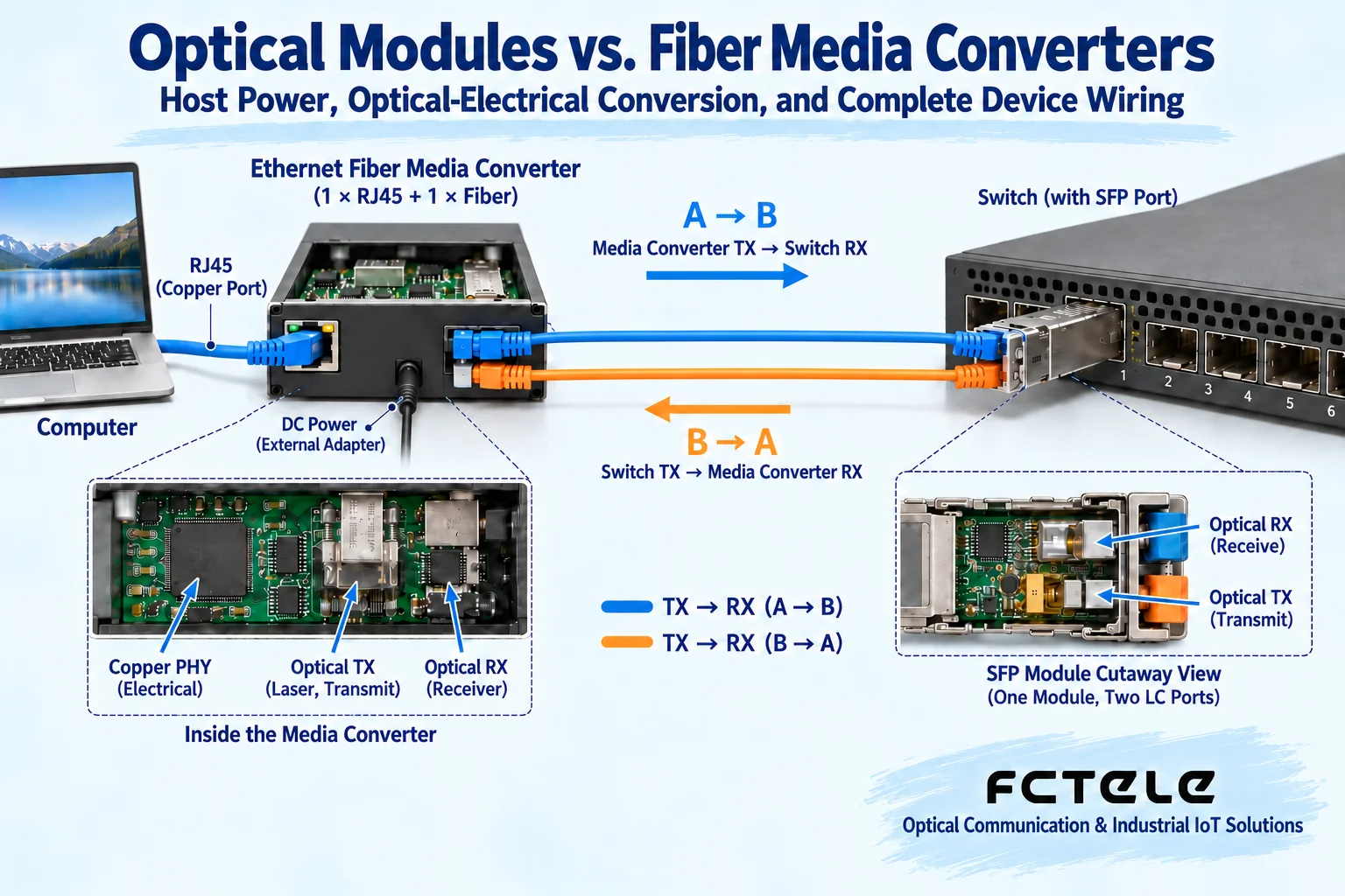
The copper-port PHY of a standalone Ethernet fiber media converter is responsible for converting signals on the RJ45 twisted pair and internal electrical signals into each other, while the optical side transmits and receives optical signals through fixed optical transceiver components or pluggable modules. The complete device may also have a bridge chip, buffer, and management circuits. Transmission and reception are bidirectional processes, and the device cannot be understood as a one-way box that only turns electricity into light. Whether the optical port is fixed, whether it supports module replacement, and how the electrical port rate is negotiated should all be confirmed from the specific model.
Feichang Technology B-series product information provides complete-device options for Ethernet fiber media converters, suitable for checking scenarios where the terminal already has an electrical port and the link needs to be extended over fiber. The power supply, optical port, rate, and supported functions in the model information must correspond separately to the actual order, and one configuration cannot be applied to all media converters. In particular, you cannot judge that the device will provide PoE power to a camera just because it has a power port; PoE capability requires additional evidence from the model and port.
How can the two ends be combined so that they may interoperate?
One common connection method is that the terminal RJ45 connects to a standalone media converter, and the media converter’s optical port connects through fiber to the SFP module of a switch at the other end. This combination does not require the two ends to look the same, but it does require the protocol, rate, optical conditions, and host support to be compatible. For dual-fiber connections, one end’s TX transmit port should reach the other end’s RX receive port; bidirectional single-fiber modules transmit and receive on the same fiber using different wavelengths, and a matching pair must be used, rather than assuming they are usable just because two units with the same label are purchased.
The checklist should include fiber type, operating wavelength, connector, transmit power, receive sensitivity, and overload range. LC and SC describe connector shapes and can be connected through suitable patch cords, but interface adapters will not change the wavelength and service protocol. The nominal distance is also not a guaranteed distance: connector loss, splice loss, line margin, and the allowable range at the receiving end all affect the link. Using a transmitter that is too strong over a short distance may also exceed the receive range, so you cannot pursue only a longer specification.
Understand the bottleneck from the actual service speed
If the rates supported by the terminal electrical port, media converter, module, and switch port differ, the link may negotiate to a lower rate, or it may not be able to establish at all. You cannot use a higher rate on the module to override the limits of other ports. Even if the physical link is successfully established, multiple terminals sharing an uplink will also compete for bandwidth, and the final effective service speed is also affected by protocol overhead, queues, servers, and application processing capability. Acceptance should use actual services and at the same time record negotiation results and port errors.
For example, if a remote control device has only an RJ45 port, while the central switch has an available SFP uplink, you can first confirm the Ethernet rate of the control device, then choose the media converter and module according to the optical budget at both ends. In a short patch-cord environment, power on one by one, verify bidirectional communication, and then migrate to the on-site optical cable. Do not connect all devices first and then judge that the entire system is normal based on one lit lamp; a lit lamp only indicates the status of a certain layer, and the service still has to go through switching, addressing, and application configuration.
Build a compatibility record before replacement
It is recommended to put the host model, firmware version, complete module order number, and fiber line number in the same record. Modules with the same appearance may correspond to different rates, wavelengths, and temperature grades, and each item must be compared one by one when replacing. First verify whether the host recognizes the module, then verify whether the remote end has a received signal, and finally check whether service frames can pass. If a spare module is used, it must also be verified before formal installation; an untested component in the warehouse cannot be directly treated as a reliable spare.
Carry out acceptance and troubleshooting layer by layer
Before installation, record the models at both ends, module labels, power specifications, and fiber routing. With the power off, check the power polarity, connectors, and cable fixation, then power on according to the instructions. First check the electrical port negotiation, then check the optical port status, and finally verify addressing, VLAN, and application communication. Clean optical interfaces with suitable tools, and do not look directly into optical ports or bring your eyes close to bare fiber. When replacing components, change only one condition at a time and keep the before-and-after states, so you can determine whether the problem is caused by the module, patch cord, or configuration.
When communication is unstable, observe error counts, service packet loss, and load changes; when digital diagnostics are available, record received and transmitted optical power at the same time, but do not treat a single power value as the entire diagnostic conclusion. Only by comparing the module’s allowable range, port statistics, and the actual service timeline can you discover insufficient margin, receive overload, copper cable faults, or service congestion. The goal of choosing equipment is to form a verifiable complete link, not to choose a more advanced answer between the two names “module” and “media converter.”
Notes on sources and figures
The main text is written based on the device working mechanism and the following sources; specific specifications are subject to the ordered model and the latest manual. The figures are general mechanism diagrams.
Cisco SFP installation and safety instructions;Feichang Technology B-series Ethernet fiber media converter information;Feichang Technology managed industrial Ethernet switch function information
Translated from the Chinese technical article. Source first published: 2019-08-21. Source last revised: 2026-10-13T19:01:44+08:00. Read the Chinese source
