


Dedicated optical terminal equipment (optical multiplexers) and Ethernet fiber media converters both use fiber for transmission, but they usually handle different services. Dedicated optical terminal equipment can carry video, telephone, serial, or other signals; the commonly mentioned Ethernet fiber media converter mainly converts the transmission medium between electrical and optical ports. To judge the difference, you should look at the service protocol, interface, and channel capability, not just whether the device has an optical port.
Two names, first corresponding to different usage habits
“Optical terminal equipment” is a broad industry term; video optical terminal equipment, telephone optical terminal equipment, and data optical terminal equipment process signals differently inside. “Transceiver” also has a broad meaning in communications; this article limits it to the common Ethernet fiber media converter to avoid confusing optical modules, wireless transceivers, and all dedicated optical devices.
For example, an analog camera outputs a video electrical signal, and dedicated video optical terminal equipment transmits it to the far end and restores the video interface; an IP camera outputs Ethernet data, and a fiber media converter extends its Ethernet link. The image can ultimately be displayed in both cases, but the signal entering the transmission device is already different, and the required supporting equipment is also different.
What exactly changes inside a device
The basic task of a fiber media converter is to let Ethernet services transmit between copper and optical media. Depending on the implementation, it may perform physical layer conversion or may have buffering and forwarding functions; you cannot say all media converters have full switching and routing capabilities. Transparent transmission also does not mean there are no rate, frame length, or latency limits.
Dedicated optical terminal equipment, on the other hand, performs electrical-to-optical conversion, digitization, multiplexing, or interface restoration around a specific service. Telephone service needs to consider power feeding and call signaling, serial service needs to consider electrical format and direction control, and video service needs to consider standard, resolution, and bandwidth. Simply converting an electrical signal to an optical signal cannot automatically complete protocol translation between these different services.
The Connectors Match—So Why Still Not Usable?
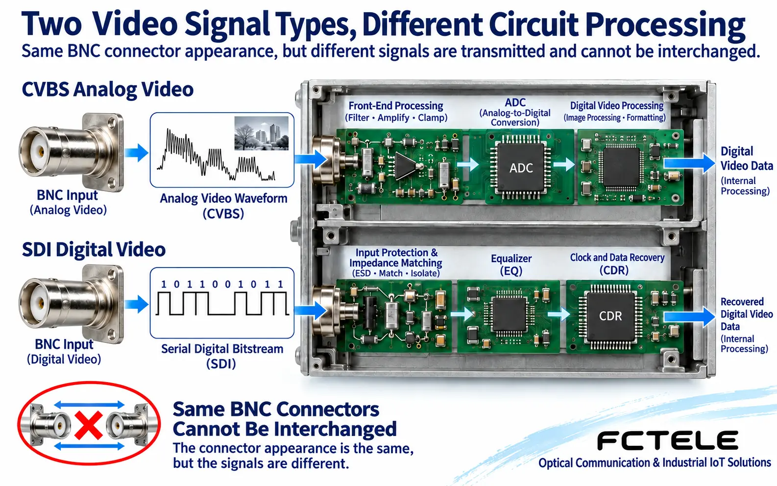
A BNC connector may carry analog video or be used for SDI or other signals; RJ45 may also appear on some dedicated interfaces besides Ethernet. Even if both ends are optical connectors, you still need to match service format, optical rate, wavelength, single-mode/multimode, and link budget. The same appearance is not proof of interoperability.
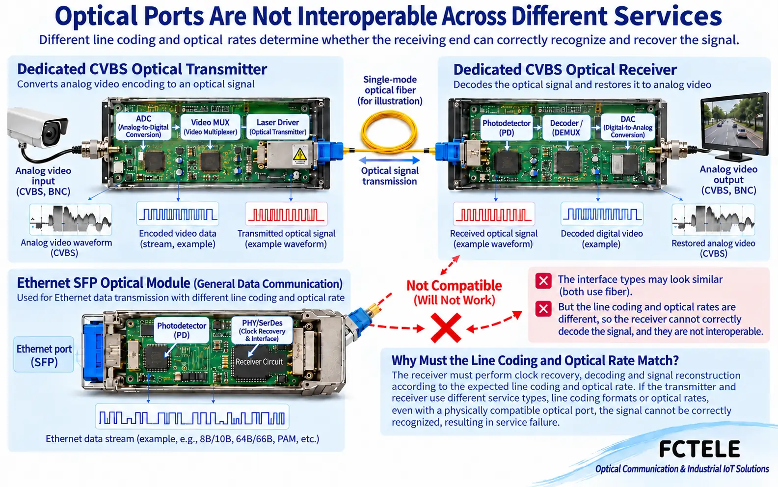
Dedicated devices usually require a compatible far end; you cannot arbitrarily connect a piece of video optical terminal equipment to a switch’s SFP port. When an Ethernet media converter interconnects with a switch optical port, you should likewise check the corresponding Ethernet standard, module capability, and transceiver conditions; different rates do not necessarily auto-negotiate to a consistent setting.
Choose by scenario, not by ranking names as high or low
If you already have analog video, telephone, or RS485 lines and need to keep the original terminal interfaces, you should look for dedicated transmission equipment around that service. If the terminals are already Ethernet devices and the main need is to extend the link, you can consider a media converter or a switch with optical ports. If multiple Ethernet terminals are aggregated, you also need to pay attention to switch ports, shared uplink, and management capabilities.
Upgrading an old camera to a network camera usually is not just replacing a pair of media converters. It may involve video encoders, address configuration, recording platform compatibility, and network bandwidth planning. Conversely, keeping a dedicated point-to-point link is not necessarily more backward; it may suit existing interfaces, a defined maintenance scope, and clear service boundaries.
Write requirements as verifiable conditions during procurement
List the terminals at both ends, interface names, number of channels, service direction, distance, and fiber conditions. For video, also state the standard and target image quality; for telephone, state roles such as FXS/FXO; for serial, state electrical standard, baud rate, and protocol. For Ethernet, state rate, allowed frame length, whether PoE is needed, and management functions.
For example, “extend one IP camera to the monitoring room” and “transmit one SDI camera video” are two different requirements. The former needs an Ethernet connection and a camera power supply plan; the latter needs corresponding SDI capability and a video receiving interface. Providing terminal model numbers and port photos together makes accurate selection easier than just saying “I want optical terminal equipment.”
Acceptance should also follow the service
Ethernet links should verify connection rate, continuous data transmission, packet loss, and the actual application; video links should verify each channel’s image and control; telephone links should test ringing, talking, and release. An optical port being lit only indicates that some physical conditions are met; it cannot replace full service acceptance. If there are management and redundancy requirements, you also need to confirm configuration saving and fault recovery separately.
A common misconception is equating fiber’s resistance to electromagnetic interference with the whole device having no interference risk at all. The device still has power and copper interfaces, so protection and installation plans should be selected according to environmental conditions. Distance is not the longer the better either; it should match actual loss and receiving range to avoid ignoring problems such as short-link overload.
Understanding “Same Appearance” from the Interface Circuit
Analog CVBS voltage changes continuously, and the receiving circuit must handle synchronization, active video, and input matching; SDI is serial digital video, and the receiving circuit focuses on equalization, clock recovery, and data decision. The two can use similar BNC connectors, but the input circuit and recovery process are different. Equalization helps improve the waveform, and clock recovery helps choose the decision timing; they cannot turn an incompatible protocol into another protocol.
Therefore, when troubleshooting, first look at the signal standard written in the manual, then choose test tools. A multimeter reading a static voltage cannot prove that the video standard or digital sequence is correct; an interface photo also cannot replace the service protocol. Actual testing requires a compatible signal source, receiving device, and corresponding instrument. If using an unknown port, you should stop and check the drawings first to avoid trial-connecting incompatible voltages.
Write clearly which far ends are compatible and which are not
An ordinary Ethernet SFP receiver expects data corresponding to the optical standard, while dedicated video transmission equipment may use its own encoding and multiplexing format. Even if the connector, wavelength, and received power appear consistent, the receiver may still not obtain valid data. There are also different modules such as dedicated video SFP on the market, so you cannot define all protocols by the SFP form factor. The limitation in the figure in this article specifically refers to Ethernet optical ports and dedicated video optical links; it cannot be generalized to all pluggable modules.
During procurement, write the far-end model, optical rate, protocol, service direction, and allowed receiving range as paired conditions. First perform a known-good short-link test, then connect the formal optical cable, and verify service ports one by one. When looking at Feichang Technology Integrated Video fiber optic transmission device, you should also determine the compatible far end according to that version’s combination of video and additional services, and not replace standard features with optional functions. Existing network terminals can refer to 1 Optical 4 Electrical Media Converter’s multiple electrical ports and MAC learning description, but they do not thereby gain video decoding capability.
Note: The images are general principle illustrations, not product teardowns, actual measurements, or certifications; specifications are subject to the actual model and on-site verification.
Translated from the Chinese technical article. Source first published: 2019-02-09. Source last revised: 2026-10-13T17:22:03+08:00. Read the Chinese source
