


Fiber media converters, fiber switches, Ethernet fiber optic transmission devices and network fiber optic transmission devices may have overlapping names, but you cannot assume they have the same functions. You should look at what signal it carries, what ports it has, and whether it provides switching and management capabilities. Media conversion, multi-port forwarding and dedicated service transmission are different tasks. When choosing a model, base your decision on functional specifications, not on the name.
First ask: what kind of signal does it carry?
An IP camera outputs network data and is usually connected through an Ethernet interface; an analog camera outputs analog video, while an SDI camera uses a corresponding digital video interface. Transmitting video content over a network and directly extending a video signal are not the same technical route. Both having the word “HD” does not prove the devices are compatible with each other.
Services such as telephone, audio, serial port and E1 also need corresponding interfaces and transmission capabilities. A network fiber optic transmission device might be an Ethernet media conversion device, or it might have multiple service ports; the specific name is decided by the manufacturer or industry custom, and is not enough to explain all internal functions.
Fiber media converters solve media conversion
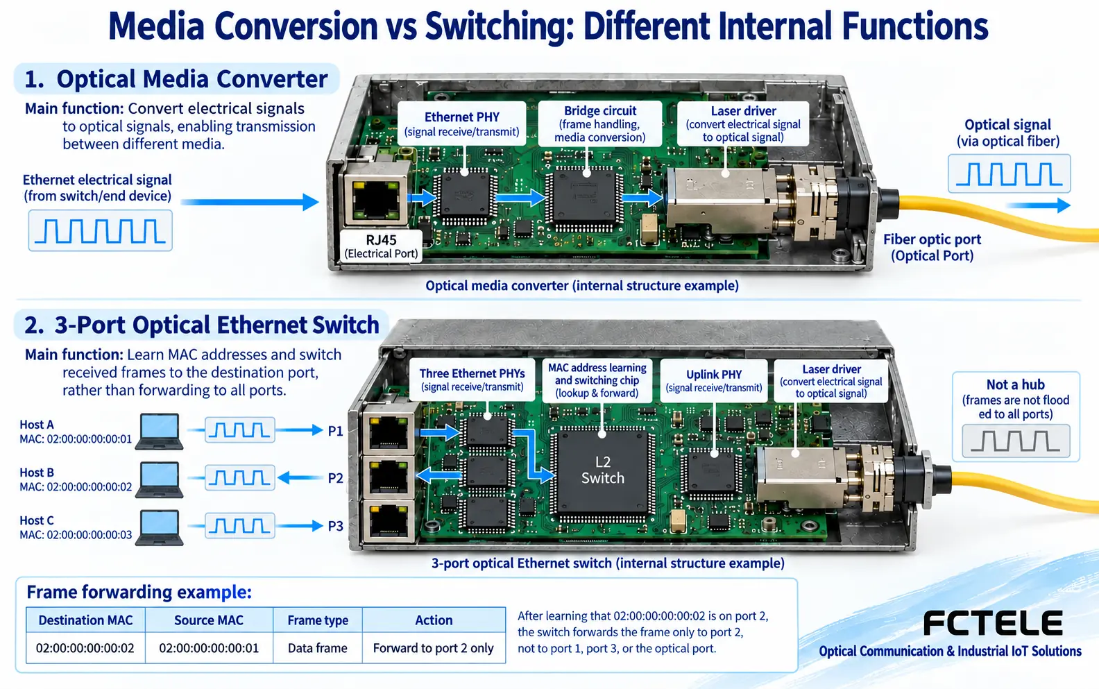
A common transceiver connects an RJ45 electrical port and an optical port, extending a section of Ethernet link from copper cable to fiber. It usually preserves the network service itself, rather than automatically turning video encoding or a serial port protocol into another application format. When connecting a camera, the camera already produces Ethernet data, and the transceiver is responsible for transmission media conversion.
A simple one-electrical one-optical device can be used for point-to-point connection; some multi-electrical-port products may internally have a switching chip and corresponding capabilities. Therefore, you also cannot assert the opposite—that all transceivers have no MAC learning or forwarding function. Whether speed conversion, management and VLAN are supported should be checked in the specific specifications.
Fiber switches solve multi-port forwarding
In the Ethernet context, a switch with multiple optical ports can aggregate multiple links and forward data according to the corresponding switching mechanism. The optical port is only the port medium and does not change its identity as a switch. If VLAN, ring network, multicast control or remote management is needed, you also need to check whether these functions exist and how they are configured.
At the same time, note that “fiber switch” in storage networks may also refer to a Fibre Channel switch, which uses a different protocol from an ordinary Ethernet switch. The same transmission medium—fiber—does not mean the two networks interoperate; you cannot directly use an FC port of a storage device as an Ethernet optical port.
“Network fiber optic transmission device” usually describes an application habit
Security projects may call equipment used for IP camera fiber access a network fiber optic transmission device or Ethernet fiber optic transmission device. If it has only one electrical and one optical port, its role may be close to a fiber media converter; if it includes multiple switching ports and management functions, its role may be close to a switch. These names are not a unified performance level.
A dedicated video fiber optic transmission device may transmit CVBS, SDI or other video signals, and cannot be directly replaced with IP equipment just because it is also used for surveillance. A multi-service fiber optic transmission device may also carry telephone, serial port and data at the same time. When selecting, confirm interface, capacity, direction and peer compatibility one by one.
Complete selection using requirements, not aliases
When only one remote Ethernet point needs to be extended, you can start evaluating from a compatible transceiver; when multiple field points are aggregated, focus on switching ports and uplink capacity; when transmitting non-Ethernet signals, choose the corresponding dedicated equipment. Single-mode or multi-mode, single-fiber or dual-fiber, speed, power supply and environmental conditions should all be written into the selection checklist.
When redundancy is needed, you also need to confirm the protection protocol and fault scope; two optical fibers do not automatically form a safe ring network. Acceptance should cover actual services and load, not just link lights. You can start from Feichang Technology Product Center to check interface and function information, and use specific models, peer devices and on-site tests to eliminate misunderstandings caused by mixed use of names.
Why do multiple electrical ports produce a shared uplink?
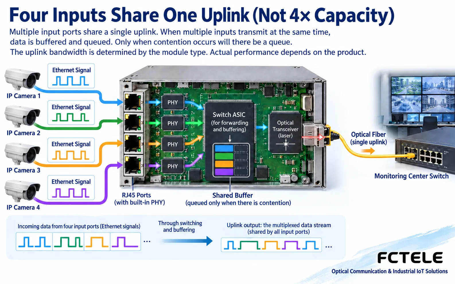
A four-electrical one-optical device has four access ports, and Ethernet frames sent from multiple terminals may all need the same optical uplink. It must decide the output port, and under contention cache or discard according to the actual implementation; an increase in the number of ports does not mean the uplink capacity doubles by that number. Continuous load exceeding available resources, or short bursts larger than caching capability, may affect services. You cannot declare that all channels are simultaneously full-speed and lossless just by looking at the negotiated speed of each port.
Feichang 1-optical 4-electrical transceiver details lists MAC learning and shared uplink. The wording in the electrical port speed section of the page is inconsistent, and should be confirmed with the current specification sheet, ordering version and actual testing. This article only uses it to explain that multi-port transceivers can have a switching implementation, and does not copy conflicting numbers. This also explains why manufacturer names cannot replace functional checks.
Learning addresses, forwarding frames and network management must be checked separately
A switching chip can establish port correspondence based on the source MAC address of received frames, and then select the exit according to the destination address. Unknown destination addresses, broadcast, multicast and VLAN boundaries have their own handling conditions, and a known unicast example cannot be understood as all frames going out only one port. Whether management configuration, multicast snooping, access control or ring protection is supported are separate model functions, and cannot all be inferred from MAC learning.
In testing, verify single-terminal, multiple-terminal simultaneous transmission and shared uplink load separately. Pay attention to packet loss, errors, short bursts and actual applications, not just a single ping in an idle state. If upgrading to a switch with optical ports, first clarify the new ports, VLAN boundaries, management interface and redundancy protocol, then check compatibility with the existing optical link. If the dedicated video input is still BNC, it will not automatically become IP video just because the device has multiple network ports.
Which terminals are affected when a multi-port optical device loses power should also be marked in the topology. Shared power supply, a common optical port and uplink failure may affect multiple services; if two fiber cores only form the two directions of transmit and receive, they are not a backup link. Do approved fault tests during the maintenance window, confirm configuration and all terminal services after recovery, and leave a baseline that can be retested.
Documentation note: The images are general principle illustrations, not product teardowns, actual measurements or certifications; specifications are subject to the actual model and on-site verification.
Translated from the Chinese technical article. Source first published: 2019-07-18. Source last revised: 2026-10-13T17:22:03+08:00. Read the Chinese source
