


How far a fiber optic transmission device can transmit cannot be judged only by the kilometer number on the package. You should first match the service and optical port, then calculate whether the loss along the route leaves margin, and at the same time check whether the received light is too strong. This article breaks the distance question into four steps: whether the service can be recognized, whether the light is sufficient, whether the receiver is overloaded, and whether the site is verified. The numbers below are teaching assumptions, do not represent the specifications of any Feichang Technology model, and cannot be used directly for ordering.
Step 1: Determine what is being transmitted, then talk about fiber distance
Video, telephone, serial port, and Ethernet optical devices all use fiber for transmission, but their input and output formats are different. A fiber optic transmission device does not automatically become an Ethernet switch just because it can transmit far, nor can it be assumed to support all rates or network management. You should record the complete models of the devices at both ends, the service format, the number of channels, the transmission direction, and the optical port option, then check the corresponding manual. When services are incompatible, even sufficient optical power cannot produce the correct output.
The fiber type, wavelength, connector, and pairing at both ends must also be checked. A dual-fiber link usually connects the transmit end at one side to the receive end at the other side, and the two directions are verified separately; a single-fiber bidirectional device requires matching transmit and receive wavelength configurations, and you cannot buy two arbitrary same-wavelength models and pair them together. If multiplexing, splitting, or other optical components exist, their loss and applicable wavelength should be included in the calculation, and you cannot measure only the length of the bare fiber in between.
Why light becomes weaker: length is only part of the loss
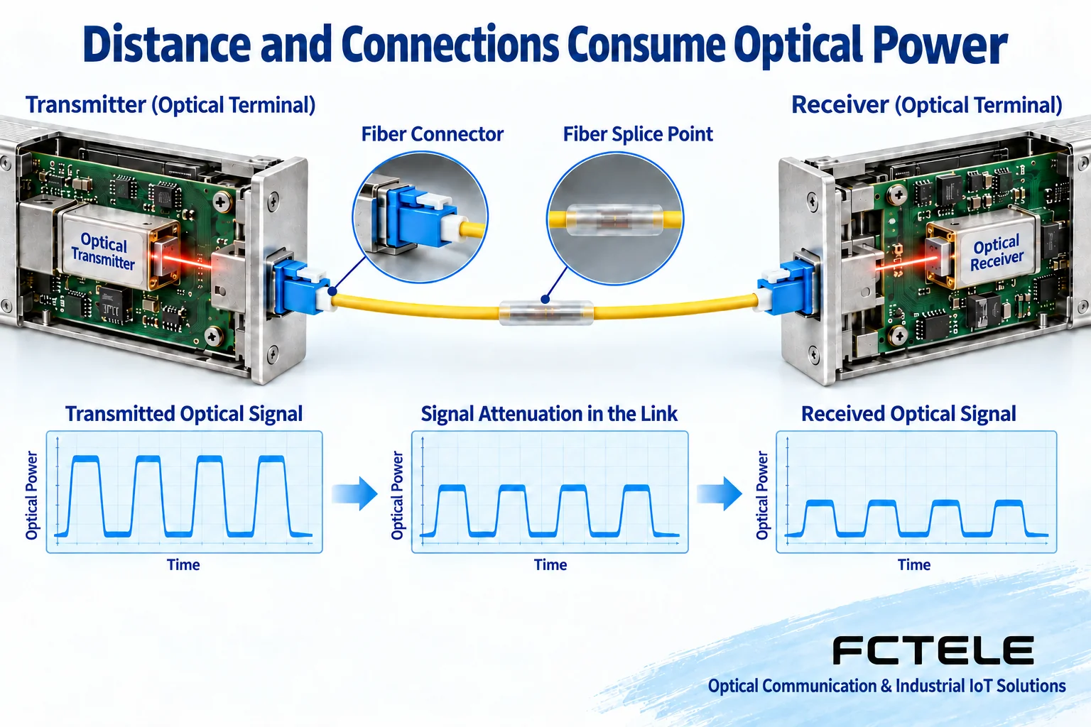
Light propagating in the fiber core gradually attenuates due to factors such as material and scattering; connectors, fusion splices, and bends may also add loss. The detector at the receiving end needs to obtain a sufficient signal under certain conditions so that the subsequent circuit can decide the data or restore the service. For two routes of the same length, if the number of connectors, the cleanliness of the end faces, and the condition of the fiber core differ, the received power may differ.
The fiber attenuation coefficient is related to fiber type, wavelength, and so on. Project data or measured data should be used, and the same per-kilometer number should not be applied to all fibers. During planning, connections, fusion splices, and other components should be listed separately; during acceptance, the entire end-to-end link should be measured as much as possible. The nominal distance of the equipment is usually based on specified conditions, and it is not a guarantee that “as long as it is shorter than this distance, it will definitely work.”
Separate dBm from dB, and the budget becomes easy to calculate
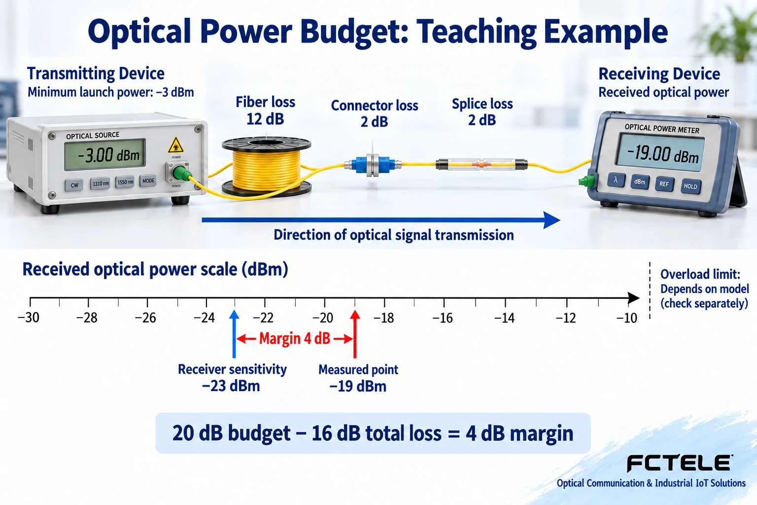
dBm expresses power relative to one milliwatt and is a way to express optical power; dB expresses a ratio and is often used to express loss or margin. In calculation, transmit power minus link loss gives the expected received power. A negative dBm value does not mean there is no light; for example, negative nineteen dBm is still a power value; but the lower the value, the weaker the power. Do not simply add the power at both ends, and do not treat dBm and kilometers as quantities that can be directly compared.
Suppose in a teaching example, the minimum transmit power is −3 dBm and the receiver sensitivity is −23 dBm. The difference between the two is 20 dB, which indicates the budget available under these assumptions for covering loss and retaining margin. Suppose the fiber loss is 12 dB, connector loss is 2 dB, and fusion splice loss is 2 dB, totaling 16 dB; the expected received power is −19 dBm, leaving 4 dB margin relative to sensitivity. This only demonstrates the calculation relationship and does not set a real fiber length or physical capability.
Planning should use the minimum transmit power and corresponding sensitivity under applicable conditions, rather than choosing the best-looking typical values. How much margin to reserve should be decided together with temperature changes, aging, maintenance, future connections, and project requirements. Having 4 dB margin does not automatically guarantee that format, dispersion, or bit error requirements will pass; the power budget solves only part of the problem, and the actual service still needs to be verified in the end.
Short distance may also fail: received light being too strong is another boundary
In addition to a lower sensitivity limit, the receiver may also have an allowed input upper limit, which is the overload condition. When a long-distance optical port uses a short patch cord, the light may be too strong and the receiving circuit cannot work normally. Therefore, you cannot assume that “a short line is definitely better than a long line,” and you certainly cannot check only the weakest power. You should use the maximum transmit power and minimum link loss to verify that the expected input does not exceed the allowed upper limit.
If an attenuator is needed, technical personnel should select it according to the specifications at both ends, wavelength, connection form, and budget. Adding attenuation will reduce the received light; you must both avoid overload and ensure that margin remains under worst-case conditions. Do not rely on repeatedly inserting adapters with unknown loss and hoping for luck, and do not treat a bent fiber as a controllable attenuation method. For links with different directions at the two ends and different optical ports, calculate separately.
Measurement and troubleshooting: power, line location, and service answer questions separately
An optical power meter can measure end-to-end received power. During testing, the correct wavelength setting should be used and the patch cord and end face condition should be confirmed. If the equipment has optical power monitoring, the measurement accuracy and location also need to be understood, and you cannot assume that all fiber optic transmission devices have this function. A single reading reflects the conditions at that time and does not prove that the link is stable over the long term; you should record the equipment at both ends, measurement points, instruments, wavelength, and actual operating configuration.
An OTDR is an instrument that analyzes line events and locations through information such as optical reflections, and it helps to find the location of abnormal loss, but its event interpretation is affected by settings, dead zones, and test direction. It cannot simply replace all end-to-end insertion loss and service acceptance. When an abnormality occurs, first check the end faces and known connections according to the procedure, then locate it with applicable tests; do not look directly at a fiber core that may carry light, and cleaning, insertion/removal, and testing should be carried out within an approved window.
If the optical power is within the allowed range but there is no service, check the input format, interface pairing, timing, and actual output; if the abnormality is intermittent, put service errors and power changes, temperature, or power supply records on the same timeline. Change one condition at a time and keep evidence before and after the change, so that problems with line loss, equipment configuration, and the service end can be distinguished.
When selecting Feichang Technology products, require complete optical port data
Feichang Technology FCV-V4T/R product page It clearly reminds that transmission distance is affected by additional loss such as the optical path and connections, and may also be limited by fiber bandwidth. This shows that when selecting, you cannot just copy the distance column. The page contains multiple fiber and distance configurations, and some optical power unit expressions need further verification; you should obtain the complete optical port data of the delivered option before calculating, and you cannot combine the maximum distance in a mixed configuration with another parameter to create a new specification.
At delivery, put the service format, optical port range, loss table, reserved margin, overload verification, and field test results in the same record. When connections are added or fiber optic transmission equipment is replaced later, recheck the affected budget and pairing conditions. The basis for a qualified distance is that suitable equipment and a reviewable link test are both established, not a kilometer number in advertising.
Reference for measurement location, end face condition, and long-term power changes Cisco optical power level measurement description, in which the models and commands are not generalized as Feichang Technology functions.
Translated from the Chinese technical article. Source first published: 2024-11-07. Source last revised: 2026-10-13T17:37:33+08:00. Read the Chinese source
