


A single-fiber converter pair is not a transmitter-only box and receiver-only box. Both transmit and receive, using different wavelengths on one core. Identify equipment and optical specifications, then compare endpoint LEDs in both directions. Do not apply a duplex TX/RX fiber swap to a single core, or declare the whole path normal from one lit endpoint.
1. How one core carries both directions
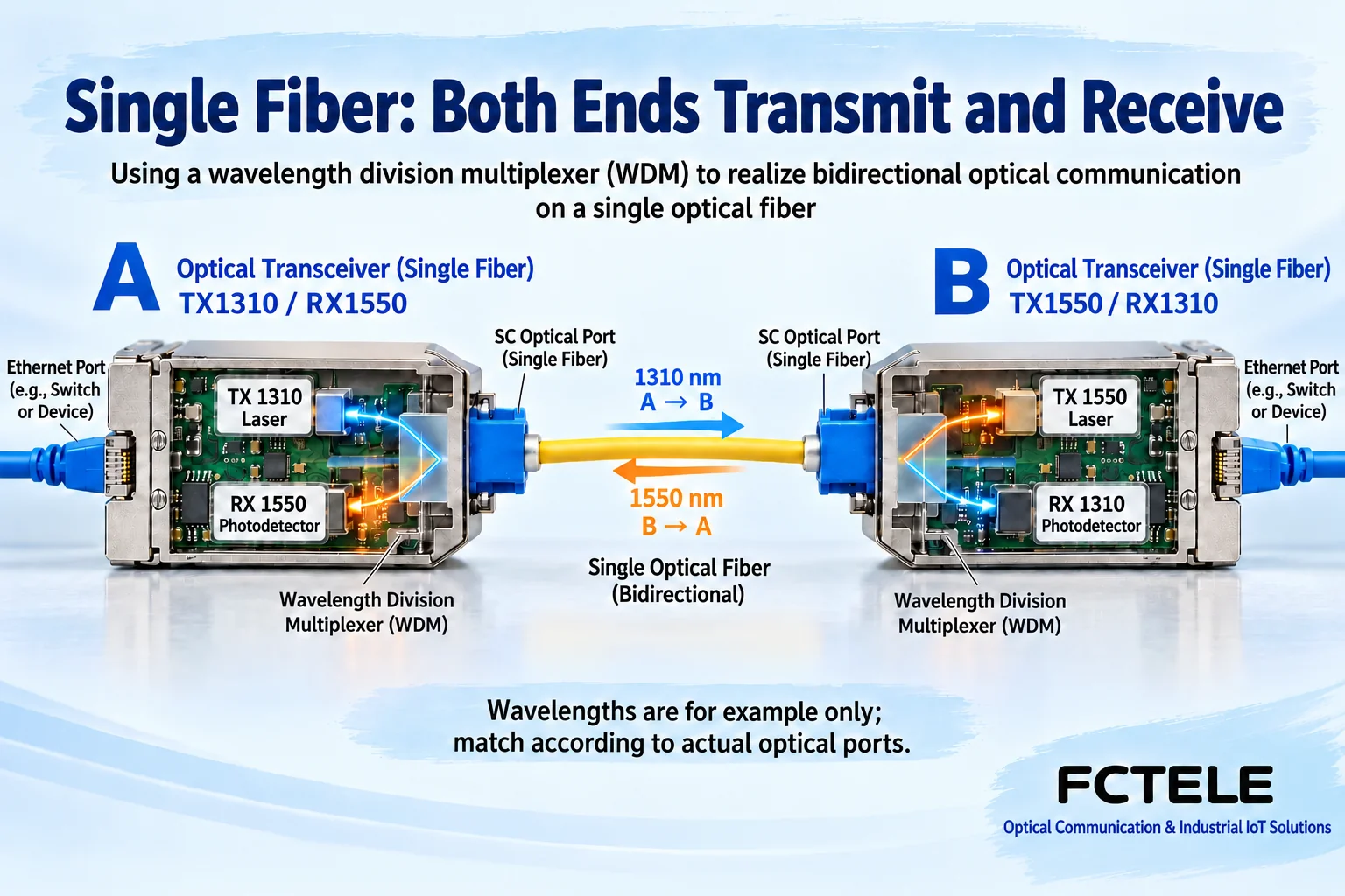
BiDi means bidirectional. The unit contains transmitter, receiver and wavelength separation. Local light enters the shared fiber; the peer wavelength is directed to reception. Copper signals continue through conversion. Colored arrows distinguish wavelength and direction conceptually; actual operating light is not necessarily visible.
For example, A may transmit 1310 nm and receive 1550 nm, requiring the reverse at B. This demonstrates complementarity, not universal single-fiber parameters. Check other wavelength combinations on labels/manuals. A/B has no cross-manufacturer universal definition. Verify local TX against remote RX and the reverse separately.
2. Pairing needs more than letters and plugs
Check optical speed, mode, connectors/polish, installed fiber and power window. A fitting connector suggests mechanical matching, not electrical/optical compatibility. Gigabit copper supporting a Fast Ethernet terminal does not imply its optical side can connect to fixed Fast Ethernet optics. Verify both media sides separately.
The FCTEL B-series single-optical/single-copper Gigabit page lists single-mode single-fiber, single-mode duplex and multimode duplex options. One series still has different optics. Specify mode and complementary peer when ordering/replacing rather than requesting a Gigabit converter alone. Where power/interface versions share a page, use exact order specifications and labels.
3. Check power, then what each endpoint receives
Endpoint PWR normally reflects its own supply. Local power cannot exclude a failed remote adapter or loose connection. Disconnect before checking plugs/terminals and match supply specifications. Do not open live equipment or look into ports. Once peer power, optics and jumpers are identified, interpret FX, FIB or the model optical-link LED.
If one optical LED is on and the other off, record endpoint, LED and fault-propagation behavior. Detection may depend on local reception, link protocol or LFP. These LEDs alone do not prove a failed transmitter at the lit end. Weak directional power, mismatched wavelengths, dirt or a receiver fault are alternatives. Trace that direction.
4. Measure both receiving directions separately
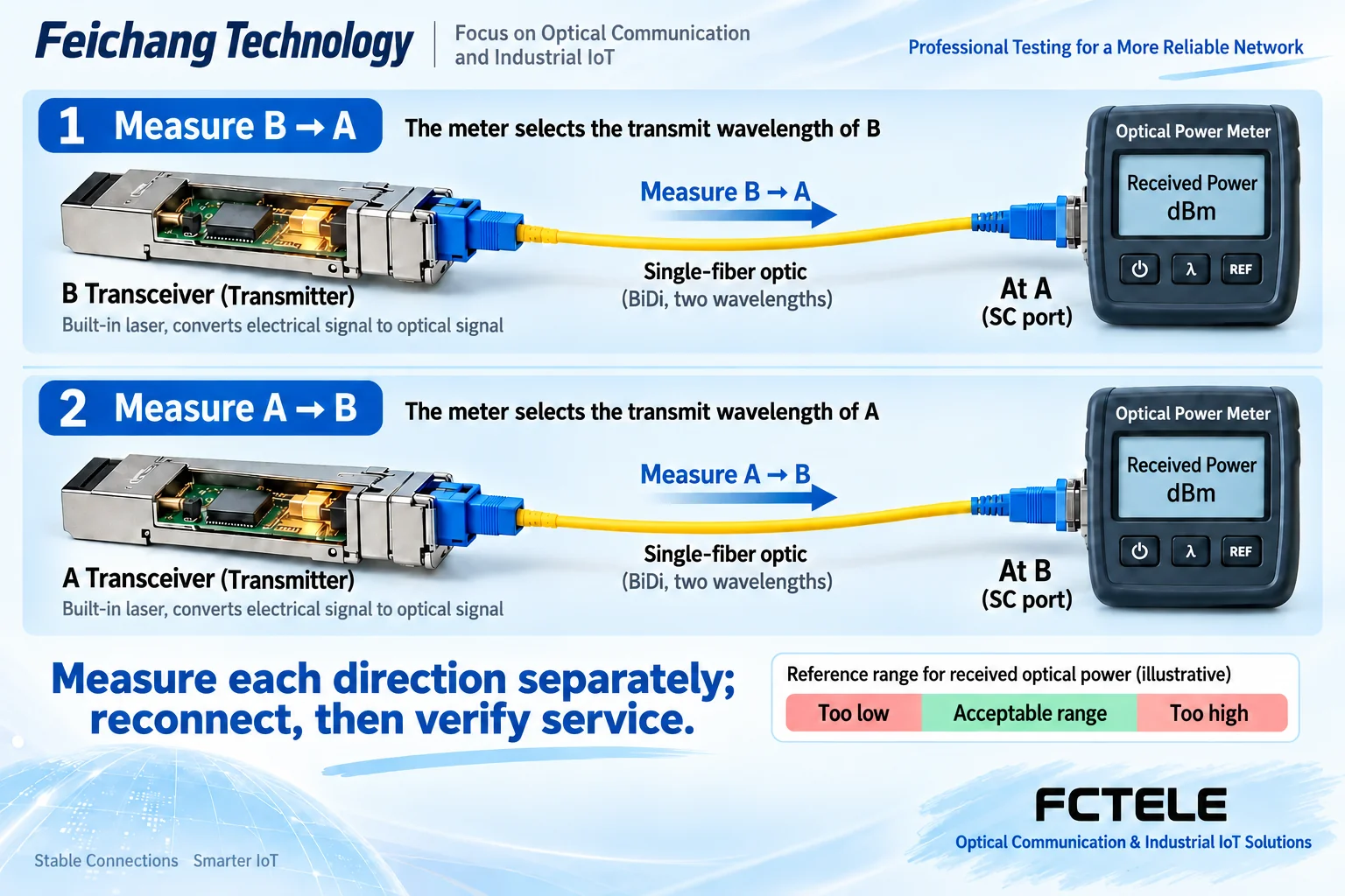
Power meters measure absolute power, commonly dBm, while loss commonly uses dB. Do not interchange units. Select the operating wavelength and suitable adapters. Since endpoints use different wavelengths, measure incoming light in each direction separately. One reading or a flashlight continuity check cannot replace bidirectional acceptance.
Weak light can fall below sensitivity; excessive light can exceed overload. Compare exact interface limits and margin rather than maximizing power. Short jumpers establish a baseline, but long-reach optics still need overload checks before short-link connection. Follow proper end-face inspection/cleaning procedures.
5. Copper and optical indicators can interact
For abnormal TP, TX or RJ45-adjacent status, check copper, peer power and negotiation too. Supported LFP can change another side link/status after one failure. A dark copper LED therefore does not necessarily prove a broken copper cable. Check optics and actual LFP settings rather than diagnosing multiple independent failures.
The FCTEL remotely managed single-optical/single-copper Gigabit series describes local/remote management and fault propagation. Appropriate versions provide status to combine with LEDs and power records. Do not assume unmanaged products expose the same data. Back up settings and confirm a window before changes; do not interrupt production casually.
6. Change one condition and verify bidirectional service
If a pair works on short fiber but disconnects intermittently on the field single-fiber route, retain equipment/settings while checking end faces, connections and both receive powers, then the field cable. Replacing both units, cable and settings simultaneously prevents identifying the effective action.
Use confirmed-compatible complementary spares, not enclosure or marketplace letters alone. Record times, endpoint LEDs, models and power for every action. Restore and test actual traffic both ways under sustained conditions. Ping shows partial reachability, not complete load performance; LEDs cannot verify IP, VLAN or permissions.
Handover should identify which wavelength each end sends, whether both receive windows pass, expected copper negotiation and actual service restoration. Saving a fiber does not remove bidirectional checks, cleaning or optical safety.
References:FCTEL B-series categories and single-optical/single-copper Gigabit details; management/LFP refer to remotely managed series details, subject to exact version. Figures show generic mechanisms and example wavelengths, not measurements or product photographs.
Translated from the Chinese technical article. Source first published: 2019-11-12. Source last revised: 2026-10-13T15:39:27+08:00. Read the Chinese source
