


Loss in a laboratory test does not by itself prove that a switch is unqualified, nor justify disabling functions simply to improve a score. First verify the tester, links, frame format and traffic model, then compare transmission and reception. This article separates test-condition problems from forwarding limits; use it separately from production congestion diagnosis.
1. Define the purpose and safe scope
Throughput, frame-loss rate, latency and burst tolerance answer different questions. Maximum laboratory performance is not identical to production application experience. RFC 2544 defines benchmark methods for network interconnect equipment. Keep high-load testing isolated; do not inject saturation traffic into a running network carrying control, surveillance or telephone services.
Confirm permitted devices, ports, firmware and configuration. Record wiring, enabled features, speed and duplex. Prepare a recovery plan and verify that the test equipment can generate and receive the planned traffic. Software generators on ordinary computers depend on NICs, drivers, processors and operating-system scheduling. A computer failing to reach line rate cannot alone establish insufficient switch forwarding capability.
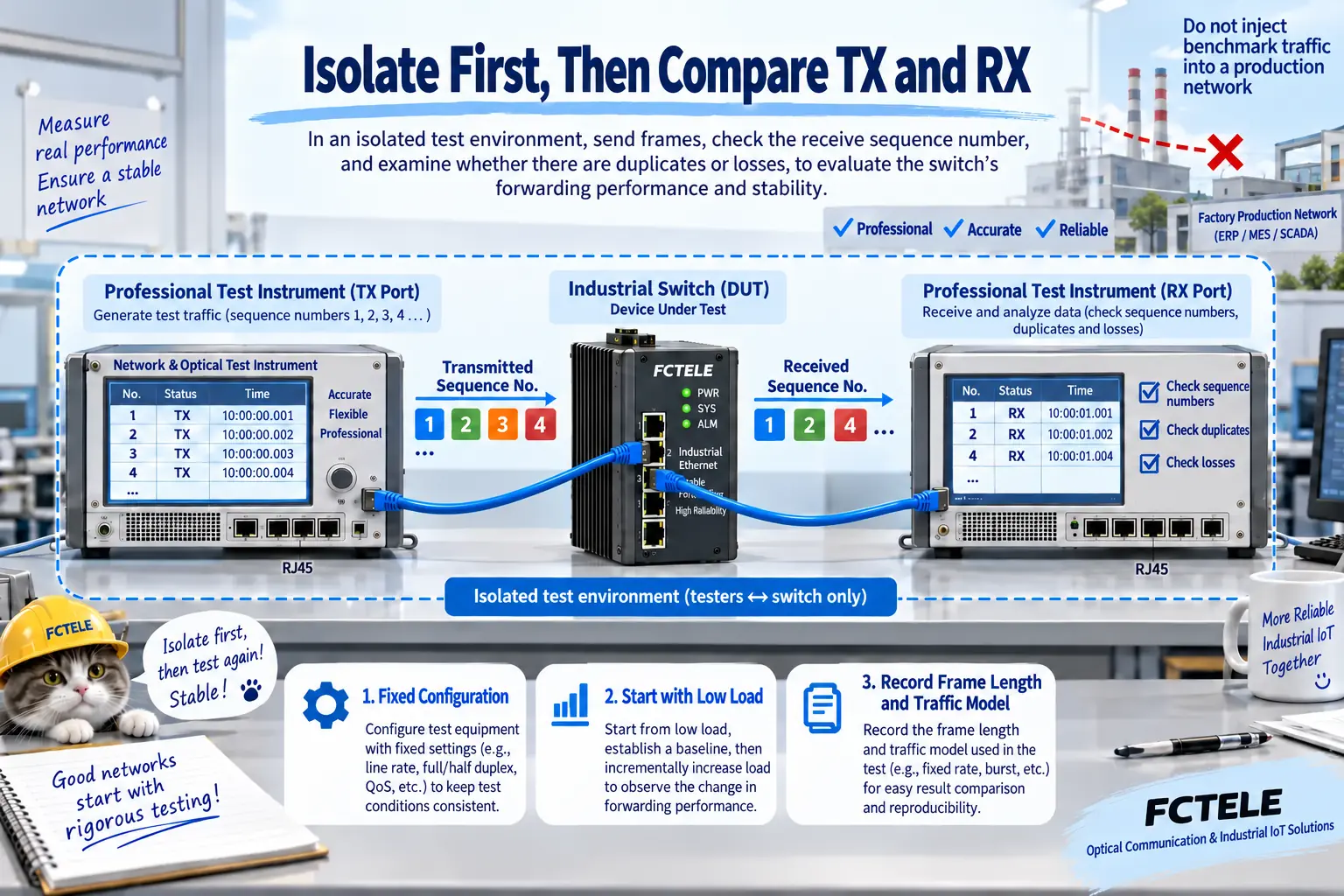
2. Count transmitted and received frames on the same basis
Establish forwarding at low load first. Check source and destination addresses, VLAN tags, frame length, payload and sequence numbers. Do not count unrelated management or background frames as test traffic. Specify whether the tester’s bit rate means occupied wire rate, Ethernet-frame bit rate or application payload rate; identical numbers can otherwise represent different offered loads.
Frame-loss rate can be calculated as transmitted minus received frames divided by transmitted frames within the same valid test set. Record duplicates, reordering and malformed frames separately. Total received counts must not let duplicates cancel losses. Allow appropriate reception time for frames still in flight after transmission stops, according to the method and instrument, so stopping reception early does not create artificial loss.
3. Investigate FCS errors as link evidence, not an assumed cause
An FCS error means a received frame fails the expected integrity check. Check whether the generator intentionally sends invalid frames, whether interfaces match, and whether cabling and modules are sound. Errors disappearing after one compatible cable, module or port substitution are useful evidence. They do not justify claiming every FCS error proves a damaged fiber, or treating egress-queue discards as the same event.
For optical links, check speed, wavelengths, fiber and transmit/receive pairing. Inspect and clean end faces correctly without looking into ports. Known-good replacement parts must still match the specifications. Where appropriate, directly connect tester endpoints for a baseline before adding the switch. This checks the test system, but cannot cover every complex application condition.
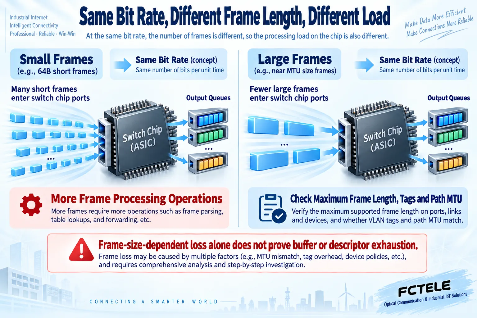
4. Small and large frames stress different aspects
At the same bit rate, smaller frames generally mean more frames and more processing operations per second. Preamble and interframe spacing also occupy line time. Do not derive maximum packet rate by dividing bandwidth by payload alone. Specify whether lengths include FCS, VLAN tags and wire overhead, and do not confuse IP-packet length with Ethernet-frame length.
Large-frame failures can involve maximum supported frame size, path MTU, encapsulation tags, test format or buffers. Small-frame failures can involve forwarding operations per second, tester capability or chip resources. Loss at one frame length alone cannot prove insufficient buffers or exhausted descriptors. Keep counters and narrow the possibilities using documentation and reproducible conditions.
5. Check address learning and aggregation distribution
Before testing many source MAC addresses, define learning, address scale and aging conditions. Unknown destinations may be flooded, changing traffic distribution from the intended unicast model. MAC capacity and lookup mechanisms vary by chip and model. Do not label every learning failure a hash collision. Inspect table entries, relevant counters and actual egress to obtain repeatable evidence.
An aggregate’s members also need not share every flow equally. Particular flow characteristics can concentrate traffic on one member, causing local congestion despite unused aggregate capacity. State flow counts and source/destination address, protocol and port combinations. Check member loads before comparing traffic models. Do not silently change hash settings to pass a test without reporting the configuration change.
6. Design comparable tests
Once a baseline is fixed, change one condition at a time: frame length, offered load, address count or port combination. Repeat and record results. Traditional Ethernet benchmarks commonly cover 64, 128, 256, 512, 1024, 1280 and 1518-byte frames. For tagged or jumbo frames, separately state length definitions, support and purpose. That traditional list is not a compulsory capability promise for every device.
Measure throughput and frame loss according to their methods, reporting duration, load increments, repetitions and the effective configuration. Do not secretly retune buffers between frame lengths or describe one port pair’s result as every port simultaneously forwarding at line rate. Multiport, cross-chip and stack paths can differ. Clearly state which paths were and were not measured.
7. Make the report independently reproducible
A complete report identifies model, firmware, tester version, wiring, enabled features, frame format, traffic model and original transmitted/received counts. Separate link errors, discards, delay and application conditions. Reproduce anomalies and preserve logs before escalation. Vendors need these conditions to locate resource or software problems, rather than a frame-loss screenshot without context.
Confirm FCTEL port rates, management, aggregation and other functions against the actual model and firmware. This article does not claim every model has passed a benchmark or exposes adjustable chip buffers. Procurement acceptance must also consider real applications, power and industrial site conditions. Laboratory qualification and stable production are related but cannot replace one another; deployment still requires controlled application validation.
Figures illustrate reviewed generic mechanisms. Equipment and instrument interfaces are not product photographs or measured results and make no performance promises.
Translated from the Chinese technical article. Source first published: 2020-11-26. Source last revised: 2026-10-13T14:51:17+08:00. Read the Chinese source
