


An optical link works with the cabinet door open, then becomes unstable after someone tidies the patch cords and closes the door. Relaxing one section changes the behavior, although its jacket is not broken. Bending and local pressure are among the factors that can change optical propagation. Understanding macrobends and microbends requires no complicated formula: follow how light is confined, what weakens that confinement, and how to test the suspected cause.
How does light follow a glass core?
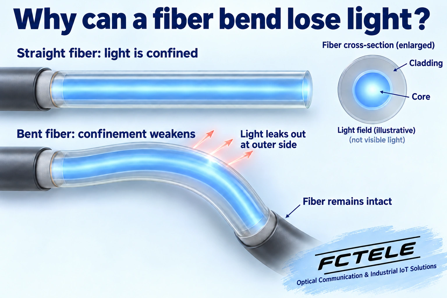
Ordinary glass communications fiber contains a central core surrounded by cladding. Their refractive indices are deliberately designed. Refractive index describes a material property affecting how light propagates. In a common structure, the core index is slightly higher than that of the surrounding cladding. Under suitable conditions, this difference supports guided propagation, so the fiber does not need to remain perfectly straight.
An introductory ray diagram often shows repeated reflection at the boundary, but a fiber is not a hollow tube lined with mirrors. Light also behaves as a wave. Its field is not cut off absolutely at the core boundary; part extends into the cladding. The optical field describes the spatial distribution of light. This helps explain how bending can alter guidance without first breaking the glass. Colored light paths in our diagrams are explanatory, not a claim that an operating patch cord visibly glows in that way.
Macrobends: why can a visible curve add loss?
A macrobend is an overall bend that can be seen, such as a patch cord turning around a cabinet corner or forming a loop in a panel. Gentle curves are normal in cabling; bending does not automatically prevent communication. With a bend that is too tight for the conditions, some energy that previously remained guided no longer follows the same confined propagation state. Some can radiate away, reducing the optical signal reaching the receiver.
A road bend needing sufficient space is a useful analogy, but light is not a car failing to turn quickly enough. The physical issue is how an optical wave interacts with a curved waveguide. Bend loss does not follow one simple linear rule for every fiber. Core design, wavelength, the length of the curved section and the number of turns can all affect the result. A visible bend alone cannot justify assigning a fixed loss value.
Microbends: pressure can matter even without a sharp outer curve
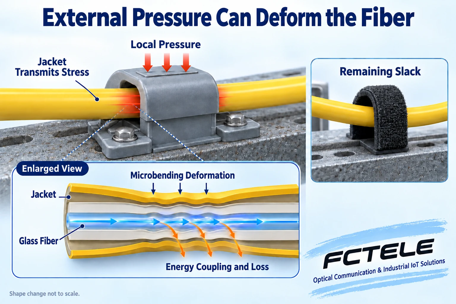
Microbends are small local deviations along the fiber axis. They may not be visible from the outside of a cable. Uneven pressure on a jacket or buffer structure, or stress arising from temperature-dependent material changes, can transfer small disturbances to the internal glass. When the axis is disturbed, energy in a guided state can couple into other propagation states, some of which contribute to loss. Coupling simply means energy transferring between propagation states.
A cable with no obvious tight outer curve may therefore still be affected by a fastening, a support surface or compression. The reverse conclusion is not valid: every cable-tie mark does not prove a microbend, and every visible small curve is not automatically a microbend. External compression can produce deformation at different scales, and severe stress can cause mechanical damage. The internal ripples in the illustration are enlarged and are not drawn to scale.
Why can an unbroken fiber still have an unstable link?
An optical receiver needs a sufficient, suitable signal under its specified operating conditions. Additional bend loss can consume the margin originally available in the link. Margin is the room left beyond normal losses to accommodate changes such as aging or connection variations. Near a limit, temperature or a small force change may alter behavior. Dirty end faces, loose connections, power problems and device faults can also cause instability. Recovery after moving a cable does not prove bending was the cause.
Both single-mode and multimode fibers can be affected, but their behavior need not be identical. Bend sensitivity can also vary with wavelength. A good result at one wavelength cannot guarantee every service wavelength is unaffected. A lower optical-power reading is a clue rather than a complete diagnosis; device monitoring has its own update interval and measurement error. Evaluate errors, lost frames, link state and the real application alongside optical readings.
Does bend-insensitive mean unrestricted bending?
A bend-insensitive design aims to reduce bend-induced loss under defined conditions. Some fibers modify the refractive-index structure, for example with a specifically designed lower-index region, to improve optical confinement. Coatings and cable construction also influence stress transfer. None of this gives glass an unbreakable shell. Low bend loss, tensile strength, compression resistance and long-term reliability are separate properties that need separate checks.
Check the exact fiber and cable designation, operating wavelengths, permitted bend conditions and connection compatibility. The words bend-insensitive are insufficient, and a demonstration involving one manufacturer's fiber cannot be applied to every patch cord or industrial media converter. Changing fiber type also requires checking the existing plant and connections. This article gives no universal minimum radius: bare fiber, patch cords and finished cables can have different restrictions.
Protect the route inside the cabinet
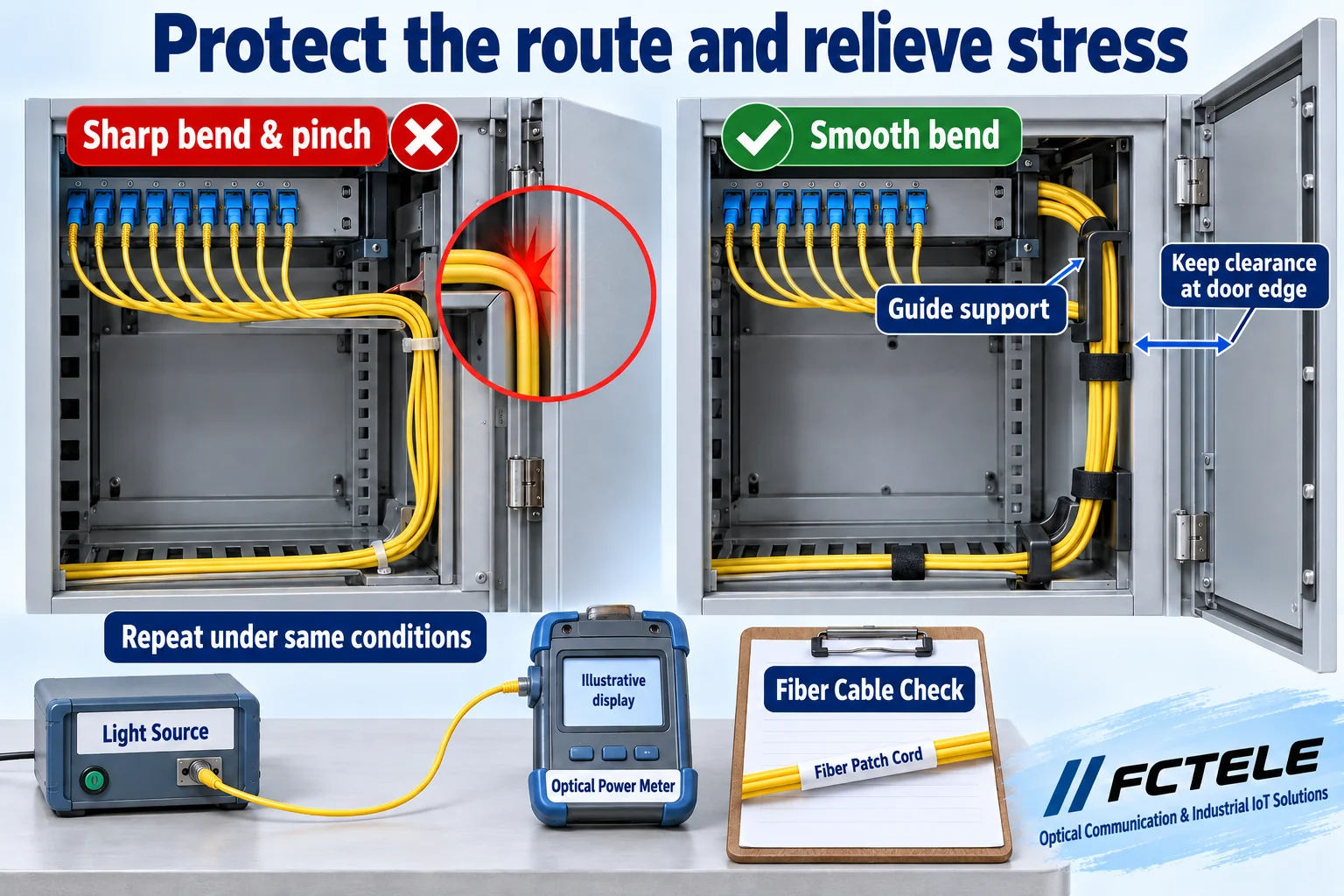
Use the cable instructions to distinguish bend-radius requirements during installation from those for long-term use. Do not confuse radius with diameter. Pulling adds tension, so its conditions differ from a cable resting after installation. Suitable guides and supports should provide smooth turns. Allow maintenance slack without forcing spare length into a tiny enclosure or forming a sharp bend immediately behind a connector.
A fastening should control movement rather than flatten the cable. Use a method suitable for optical cable and avoid concentrated pressure. Check door gaps, drawer runners, terminal covers and areas under heavy objects. A cord that curves freely with the door open may be squeezed when it closes. Inspect the whole route while withdrawing equipment or moving a door. Repeatedly kneading or sharply bending a cord to find a fault can create new damage.
FCTEL industrial optical communications documentation can help confirm real interfaces, speeds and connection methods. A media converter or switch distance rating does not replace a cable's mechanical requirements. Document fiber type, connectors, routing, supports and cable restrictions as parts of the same link. The linked real product is a documentation resource, not a claim that it removes bend loss or provides an unverified compensation feature.
Verify an improvement under comparable conditions
Record the original route, connections, optical power and application behavior. Under permitted maintenance conditions, remove obvious compression and adjust curves according to the installation instructions. Change one factor at a time. Keep the source, wavelength, connections and instrument settings consistent, then repeat the test. Save before-and-after evidence if loss improves. If it does not, continue investigating end faces, splices and equipment instead of stopping at the first visible bend.
Choose tests appropriate to the cable and instrument. Optical-power and insertion-loss tests examine end-to-end transmission changes; time-domain reflectometry can help locate events when configured and interpreted correctly. Visible red-light leakage is not a substitute for full acceptance testing, and nobody should look directly into an optical port. A reading that recovers after releasing pressure does not establish the long-term fitness of a severely pulled or crushed cable. Handle suspected damage according to its condition and maintenance requirements.
Keep the route, required radius, fastening method, test conditions and results together. Macrobends remind us to leave room for turns; microbends remind us to avoid uneven loading. A reliable link depends on more than its modules and distance: it also depends on how its glass fibers are installed and protected.
Technical references: Corning: macrobending and microbending; OFS: bend-optimized fiber FAQ; Fluke Networks: testing bend-insensitive multimode fiber; FOA: cable installation and mechanical loading. Related resources: FCTEL Technical Articles and FCTEL industrial optical communications documentation (Chinese). Original AI-assisted illustrations explain generic principles, not product internals or measurements.
