


E1 protection switching equipment solves the problem of how to keep the same service continuous between a main and a backup transmission line. It does not add the bandwidth of the two lines together, nor does it automatically change a telephone into a network phone. For PCM multiplexing equipment, leased line terminals, or conference codecs that already use an E1 interface, protection equipment can be deployed at both ends so that the service has another available transmission path. This article uses the Feichang FCCE series to explain its working process, model differences, and on-site acceptance methods.
1. First, understand what E1 and “one path of protection” mean
E1 is a digital interface with a nominal rate of 2.048 Mbit/s. When using the G.704 framing structure, data is organized into frames at a fixed rhythm; one frame has 32 time slots, each time slot is 8 bits, and there are 8000 frames per second. 32×8×8000 gives the total line rate. A time slot is like a fixed time position occupied by data, but frame alignment, signaling, and so on also occupy capacity, so you cannot directly count all 32 time slots as user telephone channels. For unframed services, the CRC4 judgment method of framed services cannot be applied.
“One path of E1 protection” means protecting one user E1 service, and it requires three logical E1 interfaces: user, main, and backup. This is not the same as the number of coaxial sockets on the panel: the transmit and receive of one bidirectional E1 interface may use different connectors, so you must count services according to port definitions, not count holes in a photo. When the line uses optical fiber or microwave for long-distance transmission, the optical modem or other transmission equipment is responsible for carrying the E1, and the protector works on the E1 interface side.
2. Why both ends must work together, not just replace one cable
In the protection working mode where both paths transmit simultaneously, the sending end sends the same user data separately into the main and backup transmission paths; after the receiving end gets two copies of the data, it selects one path to output based on quality and timing. The two paths carry a backup of the same service, not two different services, so you do not get double user bandwidth. A bidirectional service also requires the opposite direction to have the same sending, receiving, and selection capabilities. You cannot conclude that the entire leased line is normal just because the light on one direction at the local end is on.
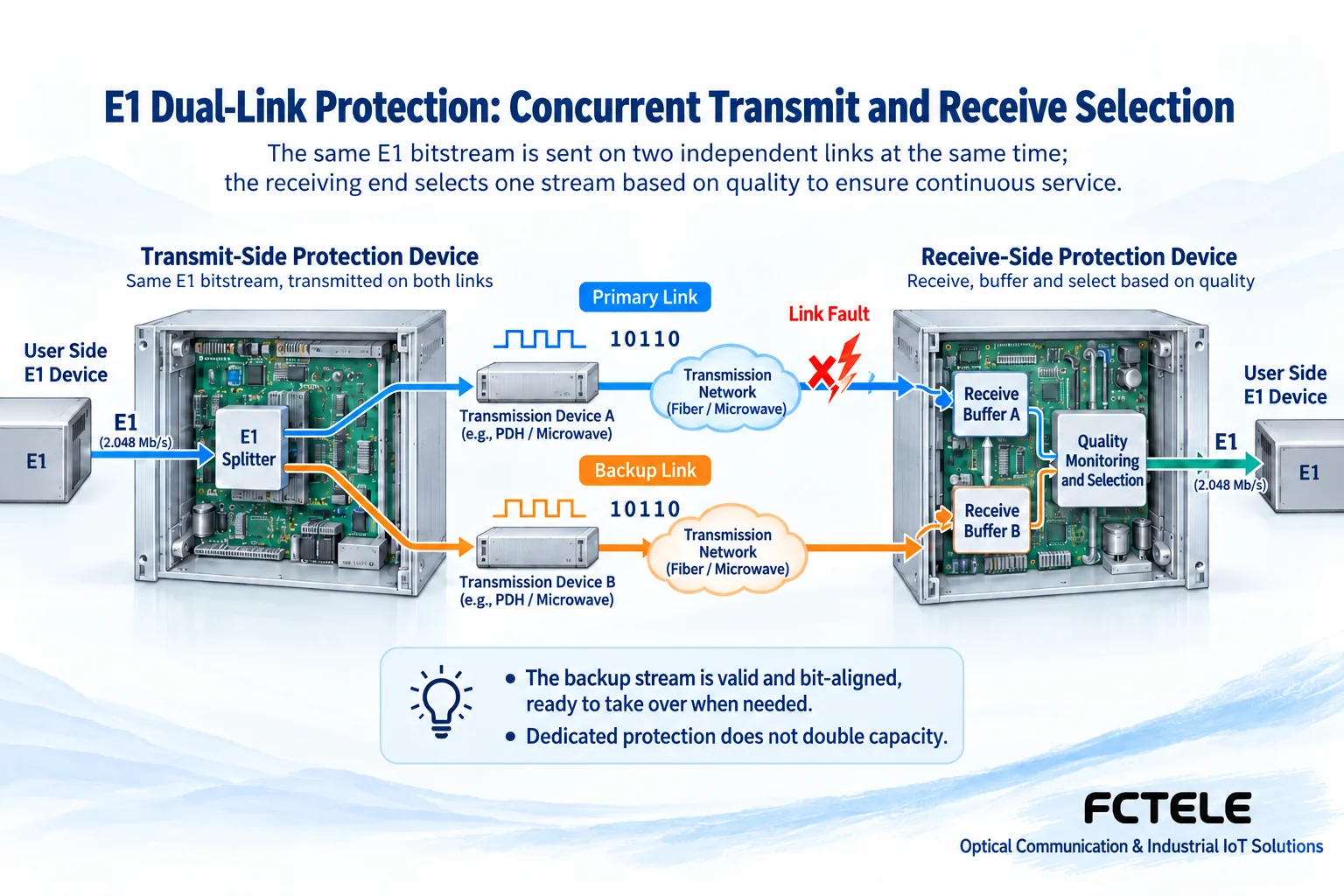
The two paths must truly reduce common failure points. If the main and backup optical cables run through the same conduit, or two sets of transmission equipment use the same unreliable power supply, then one accident will destroy both paths at the same time. Protection equipment cannot repair two optical cables that have been dug up. The Feichang product page also provides an optional configuration where “the backup does not send HDB3 code when the main is working”; HDB3 is the E1 electrical line code. After enabling this configuration, you should no longer assume that the backup always carries data that can be immediately selected and received. You must verify backup activation and the switching process according to the device instructions.
3. What conditions does “hitless switching” depend on?
The two transmission paths have different lengths and processing, so the same data fragment may arrive first from the main path and later from the backup path. If this time difference is not handled and the input is switched directly, some data may be repeated or skipped. One general mechanism for achieving continuous selection is to first recover the received data and clock, then use a buffer to align the data at the same position, and finally select the path with normal quality at the corresponding position. Buffer alignment does not turn erroneous data back into correct data, nor does it mean there is no transmission delay.
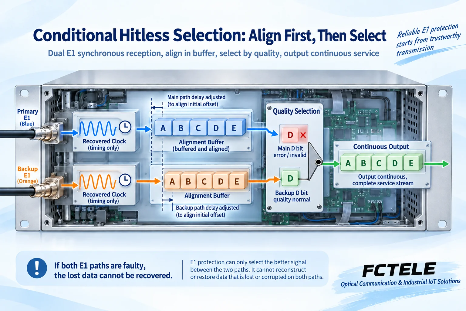
The Feichang product description uses the phrase “hitless automatic switching,” but in engineering the applicable conditions must still be clarified: the backup path is healthy, both ends are configured consistently, the path difference is within the range supported by the equipment, and the alarm trigger and recovery behavior meet requirements. The web page does not give the maximum tolerable differential delay or the recovery time under all faults, and this article does not promise specific millisecond values on behalf of the product. When the data at the same position on both paths is already lost, the selection mechanism has no third copy of data to restore it; hitless capability should be accepted based on agreed test conditions and bit error tester results.
4. How alarms tell the equipment to switch paths
LOS is loss of signal, meaning the receiving end has not received a qualified line signal; LOF is loss of frame, meaning a framed service cannot continuously identify the frame structure; AIS is alarm indication signal, which often indicates an upstream fault and should not be treated as normal user data. CRC4 is a type of check for framed services, used to detect corresponding data check abnormalities. These phenomena have different meanings. When troubleshooting, you should record which port, which direction, and which alarm appeared first, rather than interpreting all alarms as a broken optical cable.
Automatic mode triggers path selection based on device configuration, while manual mode is used to specify a path or for maintenance testing; the two cannot be mixed. FCCE-E8 can optionally have Console and independent SNMP network management, allowing you to view line status and set options such as automatic and manual switching. The management port only serves monitoring and configuration; it does not carry user E1 services, nor does it turn E1 protection into an Ethernet ring. CRC4 triggering requires matching framing mode and check configuration; when unframed data is input, you cannot rely on a frame check alarm that does not exist.
5. Selecting models from the Feichang product center
First count the number of user E1 services that need protection, then determine the installation form, interface impedance, and management requirements. The capabilities listed below come from the corresponding product pages, and optional features of one model are not treated as standard across the whole series.
| Model and product information | Services that can be protected | Key points to check when selecting |
|---|---|---|
| FCCE-E2 | 2 independent E1 protection paths | Few services; the page lists that the user and main E1 are directly connected when power is off. There is inconsistency in the description of the number of interfaces; request the specific panel and wiring table before ordering. |
| FCCE-E5 | 1–5 independent E1 protection paths | 19-inch 1U form; the page lists power-off bypass, dual power supply backup, and 75Ω unbalanced interfaces. Confirm the power supply configuration with the order. |
| FCCE-E8 | 1–8 paths, 24 logical E1 interfaces (8+16) | Many services or need for centralized monitoring; Console and SNMP are optional and are not provided by default with every unit. |
| FCCE-E34 | 4U, 17 slots, 2 paths per card, up to 34 paths | Centralized chassis project; the maximum number of paths depends on the number of cards inserted. The page describes a dual power supply chassis; check the card, interface, and power supply list. |
Some parameters on the product pages contain remnants of old templates. For example, the parameter sections for E2 and E34 still contain the wording “16 E1 paths,” which is inconsistent with their service descriptions; therefore, the clear number of service paths is used here, and physical sockets are not inferred from it. 75Ω unbalanced coaxial and 120Ω balanced interfaces cannot be interchanged based only on the shape of an adapter; the specific version, adapter, and impedance at both ends must be confirmed. The original text’s wording “carrier-class” does not mean that a certain certification has been proven, and this article does not treat web page parameters as a certification report.
6. How to accept wiring, switchback, and power-off bypass
Take a hypothetical dual-path E1 leased line as an example. First, label the user port, main port, backup port, and transmit and receive directions at both ends with the same names. Check section by section that transmit connects to the opposite end’s receive, and check impedance and clock source. First prove separately that the two bearer paths can transmit the same service, then connect the protector. Do not copy Ethernet crossover wiring, and do not use live critical services to test unknown interfaces directly. Power supply voltage, protective grounding, and polarity should still be handled according to the actual equipment instructions; do not omit safety checks just because the web page says polarity is automatically detected.
Acceptance should be divided into at least four steps: under normal conditions, record alarms on both paths, the current selected path, and the bit error baseline; in a maintenance window, create a fault on only one path and observe whether it switches to the healthy backup path; after repairing the main path, record whether it automatically switches back and whether there is repeated flapping; finally test both transmission directions and all protected services. The Feichang page describes automatic switchback after the main path is repaired by default, but it does not uniformly give the wait-to-restore timer or anti-flapping parameters, so you cannot invent a timer value and write it into the acceptance standard.
Power-off bypass is another matter: when the protector loses power, a relay connects the user to the main E1. Its purpose is to reduce the impact of protector power loss on the service, and it does not mean that automatic monitoring and main/backup selection are still retained after power loss. If the main path was already faulty, bypassing to the main path may still cause an interruption. Power-off bypass should be tested separately in an approved window, after confirming the main path is healthy and with a recovery plan; dual power supply configurations should also be tested for failure of a single power feed, rather than directly cutting power to the entire equipment room.
Finally, save the bit error tester, terminal service, and alarm records at the same time. Just seeing “no dropped calls” cannot prove that all data is error-free, and just seeing panel lights on cannot prove that the backup can take over. A qualified result should state the test service, frame mode, fault location, continuity in both directions, and recovery behavior, so that subsequent maintenance personnel can repeat the same test.
Data notes: Product capabilities are based on the above Feichang product details; interfaces and frame structure refer to ITU-T G.703 and G.704. Figures 1 and 2 are general principle illustrations, not actual products, internal circuit diagrams, or performance measurements; model configuration, line differential delay, and acceptance indicators should be based on the actual order and equipment instructions.
Translated from the Chinese technical article. Source first published: 2021-06-28. Source last revised: 2026-10-13T11:40:22+08:00. Read the Chinese source
