


Conclusion first: it can plug in, but light must also pass through correctly
When configuring patch cords for optical transceivers, the most common confusion is: What is the difference between SC and LC? Can a green connector plug into a blue interface? Can changing a cable turn single-mode into multimode? First remember four things: the connector shape determines how it is fixed; UPC/APC indicates how the end face is polished; single-mode/multimode indicates the fiber type; wavelength, rate, and optical power are determined by the optical transceivers at both ends. These conditions must be checked separately.
SC, FC, ST, and LC are all detachable fiber optic connectors. They are responsible for precisely aligning the fibers at both ends so that the light carrying service information continues to transmit. They themselves are not responsible for converting telephone signals into Ethernet, nor do they determine how fast or how far the link can run. When purchasing, writing only “one fiber cable” is usually not enough for the supplier to select the correct patch cord.
How it works inside the connector: lock the housing, precisely align the fiber core
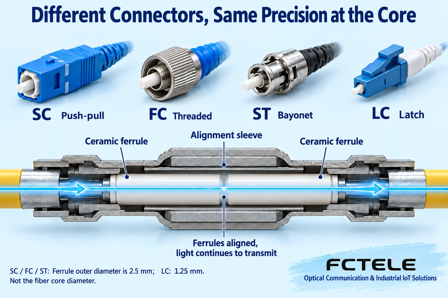
What light actually passes through is the fiber core at the center of the fiber. The ceramic ferrule at the front of the connector fixes the thin fiber in the center; when mating, the alignment sleeve in the adapter constrains the positions of the two ferrules, and the end faces contact to form a continuous optical path. The locking mechanism of the housing is responsible for maintaining the plugged state and cannot replace the internal precise alignment.
You can think of the housing as a fixing bracket, while the ferrule and sleeve perform precise positioning; but what is transmitted here is light, not metal contact conduction. Eccentricity at both ends, contaminated end faces, or poor contact will prevent some light from entering the opposite fiber core. Even if it looks tightly fastened on the outside, there may still be significant loss inside.
SC, FC, and ST commonly use a ferrule diameter of 2.5 mm, while LC uses 1.25 mm. This is the outer diameter of the ferrule and cannot be taken as the fiber core diameter. LC is therefore suitable for more compact port layouts, but “small” does not mean it is naturally faster, longer-distance, or lower-loss.
How to recognize and lock the four interfaces
To recognize an interface, first look at the device marking, then the shape and locking action. SC is a square push-pull structure; FC uses a circular metal threaded ring to screw tight, align the positioning key first and then turn; ST is a circular bayonet structure, insert and then rotate a short distance to lock; LC is small and usually has a lever-style latch, release the latch before pulling out. ST’s bayonet cannot be written as FC-style threads, nor should it be arbitrarily specified that all products rotate half a turn.
Different interfaces cannot be forcibly inserted directly. Even if some interfaces have the same ferrule outer diameter, the housing, positioning, and locking methods are different. Cross-type connections require suitable hybrid patch cords or dedicated adapters. When inserting and removing, hold the connector housing, do not pull the thin cable; when cabinet space is insufficient, consider both bending allowance and finger operating space.
SFP is a type of optical module package, not equal to all SFPs having only LC ports. The actual interface, single-fiber or dual-fiber, wavelength, and pairing requirements are still subject to the module label, device order configuration, and manual. Replacing model verification with “looks like a certain module” makes it easy to buy the wrong one.
| Interface | How to lock | Check when inserting/removing |
|---|---|---|
| SC | Square push-pull snap | Align and insert; hold the housing when pulling out, do not pull the cable |
| FC | Metal threaded ring | Align the positioning key first, then screw the locking ring tight |
| ST | Circular bayonet | Lock according to the interface bayonet, do not force it like a thread |
| LC | Small lever latch | Release the latch before pulling out, mind the space of adjacent ports |
UPC and APC: there is also an end face condition hidden after the connector name
In SC/UPC, SC is the interface type, and UPC is the end face polishing method; FC/APC is read in the same way. PC means physical contact polishing, and the end face is usually slightly convex and cannot be simply understood as a completely flat surface. UPC further improves polishing and contact quality; APC uses an angled end face, with a common inclination of about 8 degrees.
At a non-angled end face, some reflected light may return into the guiding fiber core; APC uses the angled surface to make the reflection tend to deviate from the guiding fiber core, thereby reducing return light. In the figure, the end face and optical path are enlarged for easier understanding; the actual dimensions are much smaller than the picture. Whether reflection affects service depends on the entire optical system, and digital transmission must also comply with end face and reflection specifications.
UPC and APC must not be directly mated: the end face geometry does not match, which may cause large loss, reflection, or even damage. Blue is commonly used for single-mode non-angled end faces, and green is commonly used for APC, but color can only provide preliminary identification; ultimately, look at the interface marking and supply specifications. Do not take “both are called SC” as a reason they can be interconnected.

Understand two losses: lose less light, and also return less light
Insertion loss describes how much of the forward-transmitted light is reduced after connection, usually expressed in dB; the smaller the value, the better. Return loss describes the power ratio of incident light to returned light. When expressed in positive dB, a larger value means less reflection. If the meter displays reflectance in negative dB, the more negative the value, the less reflection; first confirm which quantity the meter is displaying.
Here is a numerical example only for understanding: if reflected power is one hundred-thousandth of incident power, that corresponds to return loss of 50 dB and reflectance of -50 dB. This is not an acceptance threshold specified for all patch cords in this article. UPC/APC also cannot directly infer the insertion loss of a specific actual link; acceptance limits must come from the selected product, test method, and project specification.
How to use SC-LC hybrid patch cords: match each mating point separately
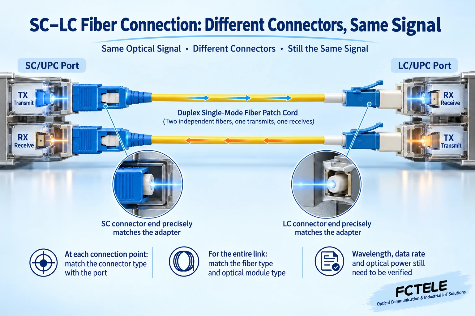
Assume one end device is SC/UPC and the other end optical module is LC/UPC, both using matching single-mode fiber and dual-fiber transmit/receive method; you can choose the corresponding SC/UPC-LC/UPC dual-core single-mode patch cord. It is no problem that the two ends of the patch cord look different; the key is that each end correctly matches the interface it is to be inserted into.
A dual-fiber link usually has one fiber responsible for one direction: local TX is transmit, connected to remote RX receive; the other goes from remote TX back to local RX. The two arrows in the figure represent the two directions respectively. For single-fiber bidirectional systems, you need to check the mutually matching transmit/receive wavelengths and A/B pairing; you cannot connect it in the dual-fiber way, nor can you conclude that two devices interoperate just because of “one fiber.”
Hybrid patch cords only change the connector type at both ends; they do not convert single-mode/multimode, wavelength, rate, or service protocol. Multimode links also need to check the specific fiber type, such as 50/125 and 62.5/125. So-called adapters only solve the specified mechanical and optical mating and cannot replace the capability of the optical transceiver. The polishing type at the two ends of the patch cord can be selected according to their respective interfaces, but each actually mated end face must match.
Selecting with Feichang Technology products: determine the model first, then write the optical port clearly
Taking the desktop 1-16 channel telephone optical transceiver FCP-O16/FCP-S16 on the Feichang Technology official website as an example, the product information lists FC, SC, ST, and LC (SFP) optical interface options, as well as single-fiber/dual-fiber and single-mode/multimode related configurations. This indicates that the series can be configured according to requirements; it does not mean that any unit in stock simultaneously has all four optical ports, or that buying an adapter patch cord can cover all configurations.
This product handles optical fiber transmission of telephone services. The telephone-side FXO/FXS and the optical-port-side SC/FC, etc., are two different sets of conditions. When connecting to an existing patch panel, provide the actual ordered model, optical port type, end face polishing, fiber type, transmit/receive wavelength, and the model at the other end to the supplier for confirmation. How interface options are implemented in a specific order is subject to the corresponding configuration list.
Check before wiring: new patch cords and dust caps also cannot guarantee cleanliness
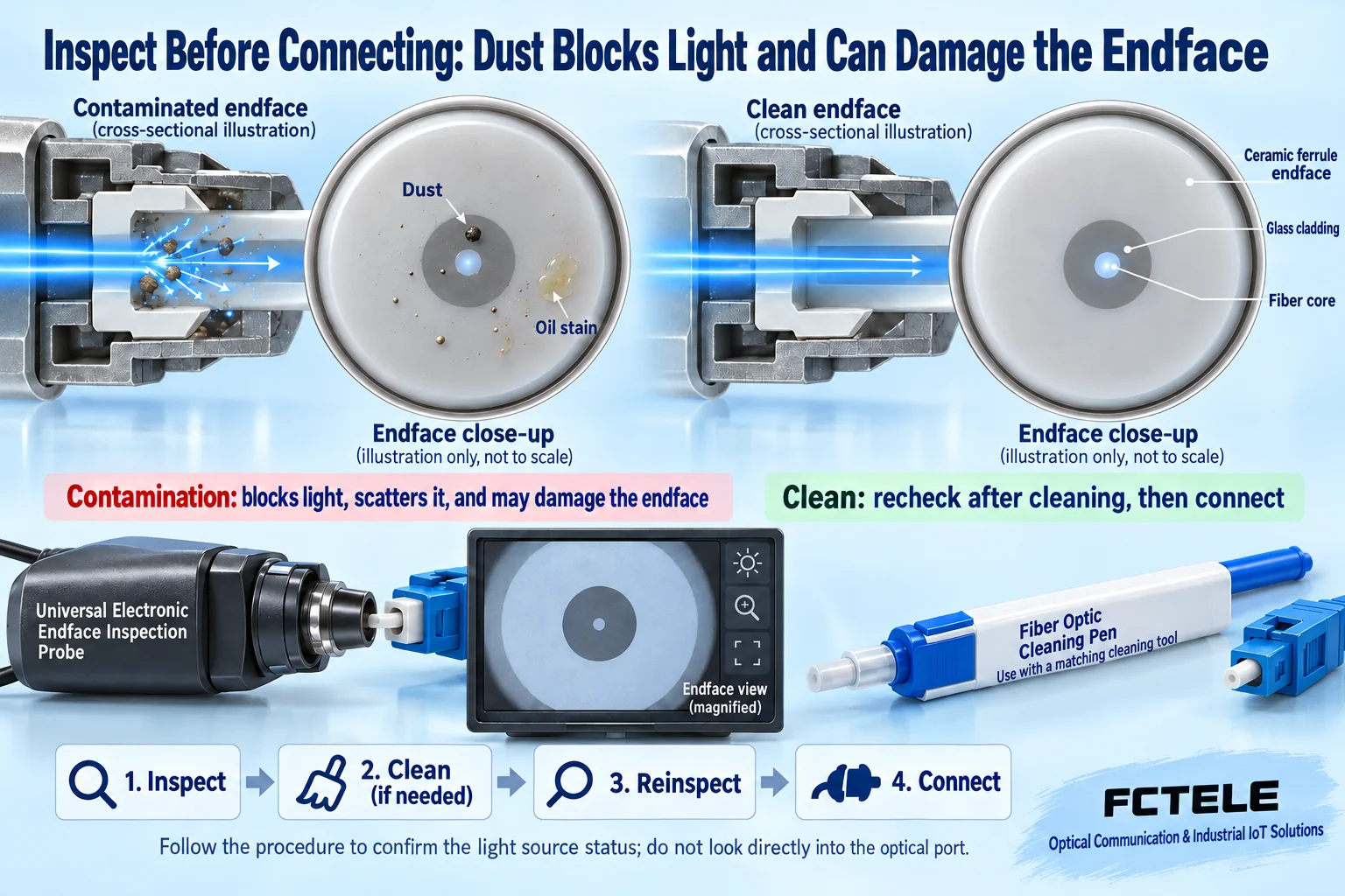
A speck of dust or a layer of oil may block the effective optical path; direct mating may also press contamination onto the other end or scratch the end face. Dust caps are for protection, but it is not that “with the cap on, it is always clean.” Newly unpacked patch cords should also be inspected according to procedures, and the end faces inside equipment receptacles also need inspection.
The correct sequence is inspect, clean if necessary, inspect again, and connect after passing. Use electronic inspection tools matching the end face type and dedicated fiber cleaning materials; do not touch the ferrule end face with fingers, and do not casually wipe with ordinary tissue. The cleaning action itself may also leave contamination, so “wiped” does not equal “inspected and passed.” If there are scratches, cracks, or it still fails after cleaning, it should be replaced or handled by a professional.
Confirm the light source status according to work procedures. Do not look directly into the fiber or optical port with your eyes to determine whether there is light, and do not use a visible light locator as an end face inspection tool. After connection, leave bending allowance for the cable to avoid being pinched by the cabinet door; the allowable bending radius should follow the specific cable information.
Procurement and acceptance: turn compatibility conditions into reviewable records
The procurement list should at least specify: models of devices and modules at both ends, interfaces and polishing types at both ends, fiber type, single-core or dual-core, length, transmit/receive wavelength and pairing relationship, and optical specifications to be met. If it is to be used in a narrow patch panel, also record connector orientation, boot, and operating space. In this way, when someone else does the wiring, it can also be checked.
For acceptance, first perform a short-distance test with a known-good patch cord, then connect the installed optical cable. Record transmit/receive optical power, link loss, connection points, and test reference method, and confirm that the received power is both above the sensitivity requirement and does not exceed the overload upper limit. The device light being on is only the first step; you also need to verify that the actual telephone or data service runs stably.
If it does not work, first check model pairing and interface markings, then check TX/RX, end faces, mating, and line loss, and replace section by section with known-good components to narrow the scope. Do not repeatedly force insertion or blindly increase optical power. Truly selecting the right connector means the mechanical connection can be fixed, the end faces can match, the optical conditions can interoperate, and the test results can be recorded.
Information note: The principle diagrams in this article are general principle illustrations and have been technically checked. They are general interface and mechanism illustrations, not actual photos or measured records of Feichang Technology products. Structure, proportions, and optical paths are appropriately enlarged; specific product configurations and acceptance requirements are subject to model information.
Verification references:
FOA: Connector structure and identification
FOA: Fiber patch cords and end face matching
Belden: UPC and APC end face reflection
Fluke Networks: Insertion loss, return loss, and reflectance
Fluke Networks: Inspect, clean, inspect again
Feichang Technology: FCP-O16/FCP-S16 telephone optical transceiver interface options
Translated from the Chinese technical article. Source first published: 2021-12-03. Source last revised: 2026-10-13T11:23:08+08:00. Read the Chinese source
