


First, write clearly who needs to access whom.
Multiple workshops need to keep their own control networks while also letting a maintenance server read data from specified devices. In this case, you can consider using an industrial Layer 3 switch at the aggregation location. It can connect different IP subnets according to configuration and provide corresponding management and policies. Having “Layer 3” in the device name does not mean all services should cross subnets, nor does it automatically bring protocol translation, motion synchronization, or complete network security.
First list the PLCs, operator panels, cameras, recording servers, and maintenance computers. Write down which devices communicate directly, what services they use, and which access must be prohibited. Only by separately planning the control communication that must stay local and the data exchange that crosses workshops can you decide where the gateway goes and how much traffic the uplink must carry. The examples in this article are used to explain mechanisms, not actual measured results from a specific customer project.
VLANs separate broadcasts, gateways connect subnets
A VLAN is a logical division of a Layer 2 network. Within the same VLAN, the switch forwards Ethernet frames based on learned MAC addresses and port relationships; broadcast and unknown destination traffic is limited by the VLAN it belongs to and the forwarding rules. Uplinks between switches can carry multiple VLANs with tags, and both ends must agree on the same allowed list and tag handling. Grouping ports is not the same as encrypting data.
Different IP subnets require a routing gateway. A Layer 3 switch can provide a logical Layer 3 interface for applicable VLANs, often called an SVI, and endpoints set its address as the corresponding default gateway. A management address used only for managing the device does not prove it can route services. VLANs, interface status, endpoint addresses, and forwarding functions must all meet the working conditions of that model. You cannot simply fill in a gateway address and consider the network complete.
Routing and access permission are two separate decisions
When an endpoint accesses another subnet, it places the IP packet into a frame whose destination MAC is the gateway. The gateway takes out the packet, selects the next hop and egress based on routing information, and then forms the frame header needed for the next link. Ordinary routing does not automatically change the endpoint IP into the gateway IP; address translation is a different type of processing. The routing table says where to go, and neighbor information says how to deliver on the next link. They are not the same table.
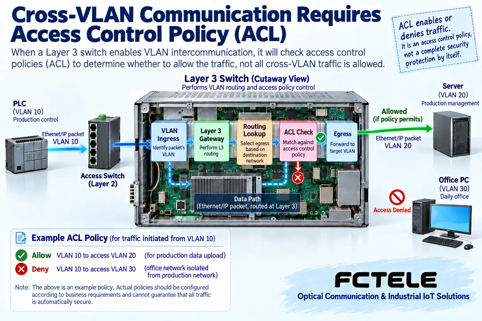
ACL stands for Access Control List. It can decide which packets are allowed or denied based on supported fields. When configuring, clearly define the match target, the applied interface, and the direction, and also consider return traffic. In the figure, allowing production line access to the server and denying access to the office area is an independent policy example. It does not mean all Layer 3 switches have this rule set at the factory. Cross-subnet connectivity alone cannot prove that isolation goals are met; an ACL is also not equivalent to a firewall that includes full session inspection and application identification.
Whether control protocols can cross a gateway must be checked separately
Industrial devices may use communication methods that depend on Layer 2 broadcast, multicast, or special frame handling. Ordinary IP routing does not automatically forward all Layer 2 discovery and control traffic, nor does it translate one industrial protocol into another. You cannot claim that all PROFINET, EtherCAT, or robot control tasks can operate across gateways just because the switch supports Ethernet. You should check the endpoint protocol, network structure, and vendor deployment requirements.
For systems that need synchronization or deterministic timing, you must also confirm that the entire path supports clock, latency, and latency variation. Supporting a certain priority field does not equal providing complete deterministic network capability. Multicast across subnets also requires applicable routing and receiving conditions. Layer 2 multicast snooping cannot be directly treated as Layer 3 multicast routing. Keeping service boundaries is usually easier to verify than splitting all control devices into different subnets.
The shared egress determines actual congestion
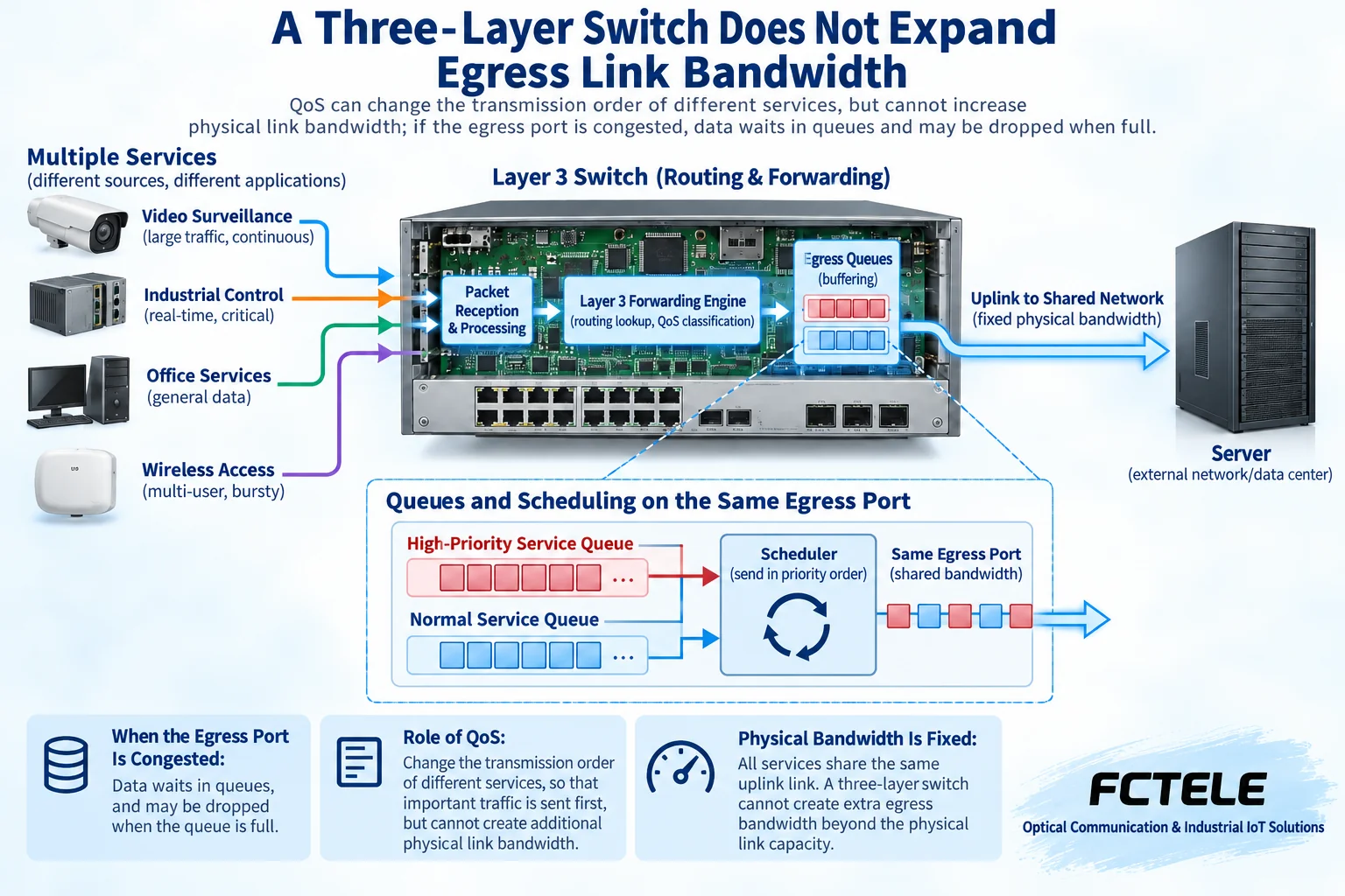
When multiple cameras, production data, and file transfers converge to one egress at the same time, they all use the actual bandwidth of that egress. Layer 3 routing does not expand the physical port rate, and adding more VLANs does not make subnet bandwidth unlimited. You should count which shared links each service passes through, distinguish average load from possible simultaneous peaks, and not just look at the number of access ports.
QoS is a quality of service mechanism that classifies and schedules packets according to rules. It can affect egress transmission order or resource allocation, but it cannot create extra bandwidth. Sustained overload can still cause queuing, packet loss, or response changes. When configuring priority for critical services, you should also check the classification basis, queue rules, and the minimum needs of ordinary services. The queues in the figure are a mechanism illustration; the specific number and scheduling method depend on the model implementation.
Industrial reliability requires multiple conditions to work together
Dual power supplies are used for power redundancy, link protection is used for transmission path changes, and gateway redundancy is used for gateway role takeover. These mechanisms handle different failures. Two switches repeatedly configured with the same ordinary gateway address will not automatically form reliable active/standby operation. Loop protection and routing convergence cannot be mixed into a single recovery time promise. You should check the mechanism used, configuration consistency, and the acceptable interruption range for the service.
During installation, also pay attention to power, protective grounding, heat dissipation, cabinet temperature, vibration, and optical module conditions. You cannot infer that all environmental requirements are met just from an industrial-grade name. Back up configurations and save firmware versions, wiring labels, and maintenance access. Use recoverable steps for changes; before verifying failover in a production network, arrange an allowed maintenance window. Do not directly impact critical services with full-load testing.
Check functions against specific Feichang Technology products
The Feichang Technology 10G 4-optical 8-electrical Layer 3 managed switch page lists functions such as optical and electrical interfaces, IP routing and Layer 3 ports, VLAN, ACL, and QoS queues. It can serve as a reference object for workshop aggregation design. Layer 3 interfaces are used to connect service subnets, ACLs are used to enforce specified access, and optical ports provide applicable uplink carrying. Functions must be matched to the exact hardware, firmware version, capacity, and configuration requirements, and must not be transferred to ordinary Layer 2 models.
The page also lists dual power supplies and corresponding protection functions. The operating temperature statements in different places on the public page differ, so during procurement you should ask the manufacturer to confirm the delivered specification and not choose a wider value on your own. Optical module rate, type, and received power need to be checked separately; optional power supply functions do not mean all ordered models include them. A manufacturer function list also cannot replace verification under actual service load.
Acceptance with one allowed path and one denied path
For example, place production line control devices in VLAN 10, the maintenance server in VLAN 20, and office terminals in VLAN 30. First confirm communication within each VLAN, then establish the required gateways and routes, and finally add policies that allow the production line to upload data to the server and restrict production line access to the office area. Addresses, service ports, and return paths are filled in according to the actual project. The VLAN numbers in the diagram do not have fixed purposes. Testing should cover the real allowed data upload task and the access that must fail.
Delivery records should keep the topology, ports and labels, address and gateway tables, routes and policies, configuration backups, and actual test conditions. Besides reachability, also test the response of agreed services, peak load, and allowed fault recovery. Being able to open the management page or occasionally ping successfully only proves that limited conditions hold; a formal conclusion should correspond to the already verified device combination and service scope.
Documentation note: The principle diagrams have been checked for technical content and are used to explain general mechanisms. They are not product photos or measured records. Specific interfaces, modes, and capabilities are subject to the selected model, version, and on-site verification.
Verification references:Cisco inter-VLAN routing and gateway configuration guide
RFC 1812: Requirements for IPv4 Routers
Feichang Technology 10G 4-optical 8-electrical Layer 3 managed switch
Feichang Technology Layer 3 managed switch product category
Related technical topics:What is the difference between Layer 2, Layer 3 switches, and Layer 4 load balancing: forwarding information and connection stateHow to choose between Layer 2 and Layer 3 switches: forwarding principles and performance boundaries
Translated from the Chinese technical article. Source first published: 2024-06-06. Source last revised: 2026-10-13T11:37:04+08:00. Read the Chinese source
