


First confirm which type of MSTP this is
In traditional optical transmission networks, MSTP often describes an SDH-based multi-service transport platform. It accesses and carries different services within a synchronous transmission hierarchy, with common objects including E1 and Ethernet. In Ethernet switch documentation, MSTP usually refers to the Multiple Spanning Tree Protocol, used to organize Layer 2 loop-prevention paths. The abbreviation is the same, but the device responsibilities and internal processes are different. Before selection, the complete technical object must be clearly written.
A multi-service platform does not mean that any connector or any protocol can be transmitted directly without adaptation. Services require supported access interfaces, processing modules, and transmission resources. Older articles summarized interface requirements as having no special requirements, which easily leads readers to ignore rate, framing, electrical, and mapping relationships. Optical fiber is only the medium; whether interworking is possible also depends on the complete line system carried over it.
How different services enter synchronous lines
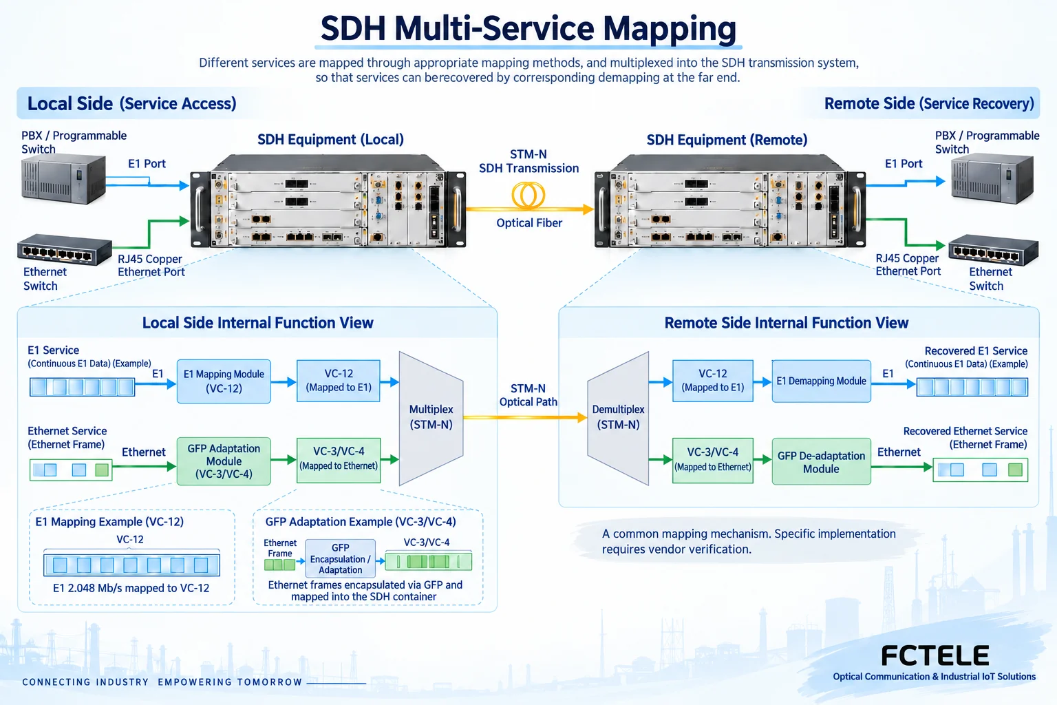
SDH organizes line data according to standardized synchronous frames and carries mapped services through structures such as virtual containers. A virtual container can be understood as a structured position arranged by the transmission system for a certain type of service; it is not an Ethernet VLAN, nor is it an optical wavelength. After E1 access, it needs to be sent to the far end according to the corresponding mapping, cross-connection, and channel configuration, and then restored at the corresponding service port.
Ethernet is a packet service that works in frames and needs adaptation when entering this type of transmission system. The Generic Framing Procedure (GFP) is one related adaptation mechanism, but merely having MSTP written on a product does not guarantee that all versions implement the same mode. Specific products may support different encapsulation, virtual concatenation, or capacity adjustment functions. The actual board and peer configuration should be checked; similar function names cannot be used as proof of interworking.
Interface rates and bearer resources must be calculated separately
A service port marked as gigabit indicates a type of capability on the interface side; it does not prove that it has obtained a complete gigabit usable channel in the transmission platform. Resources allocated by the platform, structures shared by multiple services, cross-connection capacity, and processing modules may all create limits. When multiple ports work at the same time, actual resource allocation and egress load should be calculated, rather than directly adding the rates of each service port.
The nominal line rate of E1 is 2.048 Mbit/s; structures such as framing and signaling affect the data available for actual services. Ethernet also has frames, protocols, and possible adaptation overhead, so accurate remaining capacity cannot simply be obtained by subtracting interface numbers from line numbers. The selection checklist should separately list port types, number of service channels, allocated resources, and conditions for simultaneous operation, and then carry out representative load verification.
For example, when a group of telephone services and a group of surveillance Ethernet services are accessed together, first clarify the continuous capacity and allowed latency required by each, then check which resources the corresponding boards can allocate. Telephone channel mapping should not be arbitrarily mixed with video traffic in calculations, and the average video load is not equal to all instantaneous peaks. During acceptance, run both groups of services at the same time and separately save channel quality and network counters; only then can shared-resource limits that are invisible during individual test connections be found.
The E1 side must verify electrical and timing relationships
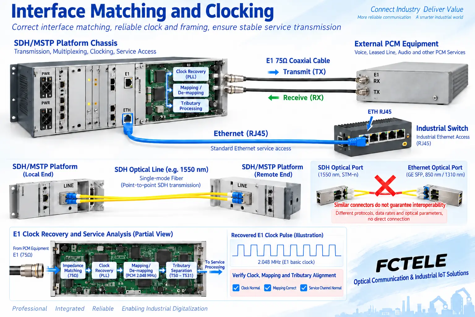
E1 commonly uses 75Ω unbalanced coaxial and 120Ω balanced interfaces, which need to match the port definitions at both ends. Impedance must not be ignored just because a connector can be inserted. Transmit connects to the peer receive; specific pins, framing mode, CRC4, and channel configuration should be checked separately. Ordinary RJ45 Ethernet and some E1 interfaces that use the same shell cannot be arbitrarily interconnected.
Continuous digital services require clocks. The project should clarify which device or network provides timing, which port recovers and uses the received clock, and how it works when the reference is lost. Uncoordinated clocks may cause slips or service abnormalities; a lit optical path light does not prove that the timing relationship is correct. Different service clocks and internal device synchronization may also use different implementations, and these conditions cannot be omitted just by drawing an optical fiber.
Ethernet and optical lines cannot be judged only by slots
For Ethernet service ports, confirm port rate, duplex, VLAN tags, frame length, and handling of required control packets. So-called transparent transport preserves the required service semantics within a specified range; it does not mean that all frame types, arbitrary sizes, and arbitrary peaks pass unconditionally. When cross-group routing or security policies are required, it should also be confirmed at which node these functions are placed.
Line-side SDH optical ports and Ethernet optical ports may use module form factors that look similar, but they still belong to different line signals. STM level, interface specifications, optical parameters, and peer version should be checked; interworking cannot be assumed just because an optical module of the same rate is inserted. Optical budget and receive range are another set of conditions, and should be verified separately from SDH frame structure, mapping mode, and network management compatibility.
How Feichang Technology devices are positioned on the access side
The documentation for Feichang Technology numbered 78, the FC2PM-O64/S64 modular multi-service telephone optical multiplexer, lists service slots as well as E1, telephone, and different Ethernet configurations, and can be used to check specific service access and multiplexing requirements. However, multiple interfaces and modularity do not automatically prove that it is an SDH/MSTP platform, nor do they prove that it supports all GFP or SDH cross-connection capabilities. Ordering should be checked against a clear model and board combination.
If E1 services from this type of device are to be handed over to an existing SDH node, the E1 port, electrical mode, timing, framing, and channel allocation should be confirmed channel by channel; Ethernet services should be accessed to the corresponding node through their actual service ports. The number of interfaces, line capability, and options of one product configuration cannot be generalized to the entire series. When MSTP is truly required, ask the supplier to provide documentation for the corresponding transmission platform, and avoid replacing it with the name of an ordinary multi-service optical multiplexer.
Complete interworking acceptance by service layers
First verify the local E1 or Ethernet service separately, then bring up a single transmission channel and confirm the corresponding far-end port and direction. Then add other services and check simultaneous load, alarms, and management. During line fault and recovery tests in a maintenance window, observe the line layer, mapping channel, and actual application at the same time; do not treat normal network management display as proof that all services have recovered.
Save boards and versions, service ports, channel cross-connections, optical parameters, and clock sources. For E1, verification can combine bit errors, loopback, and terminal service checks; for Ethernet, check packets, tags, throughput, and drops. When a fault occurs, troubleshoot segment by segment along the interface, transmission resources, mapping, and application; do not attribute all incompatibility to fiber quality or the need for higher optical power.
Documentation note: The principle diagrams have been checked against technical content and are used to explain general mechanisms; they are not product photos or measured records. Specific interfaces, modes, and capabilities are subject to the selected model, version, and on-site verification.
Verification references: ITU-T G.7041 Generic Framing Procedure
ITU-T G.707 Synchronous Digital Hierarchy interfaces
ITU-T G.703 Electrical characteristics of digital interfaces
ITU-T G.704 Synchronous frame structures
Feichang Technology FC2PM modular telephone optical multiplexer
Feichang Technology modular multi-service telephone optical multiplexer category
Related technical topics: How to distinguish switch stacking and cascading: logical devices, uplink capacity, and fault boundaries How to distinguish E1, channelized E1, and PRI: time slots, signaling, and access acceptance How MEMOBUS serial ports run over fiber: message transparent transmission, transmit/receive timing, and device verification
Translated from the Chinese technical article. Source first published: 2021-06-28. Source last revised: 2026-10-13T01:08:12+08:00. Read the Chinese source
