


First, identify the protocol and the electrical interface
MEMOBUS is used for serial communication in some industrial drive and control devices, and related manufacturer documentation often lists MEMOBUS/Modbus together. The protocol defines requests, responses, and data access methods, while RS485 describes a type of electrical interface. When preparing to change the link to fiber, you should first confirm the actual protocol mode and wiring used by the controller and the inverter, rather than assuming all commands are compatible just because you see RS485.
Registers, functions, addresses, and communication settings may differ between devices. A manufacturer’s manual stating RTU mode or a certain baud rate cannot be generalized as a unified capability of all MEMOBUS systems. The 4 Mbps figure in the old article lacks evidence consistent with the target device mode and is not used here; nor can high-speed fieldbus rates from other similarly named systems be directly transferred.
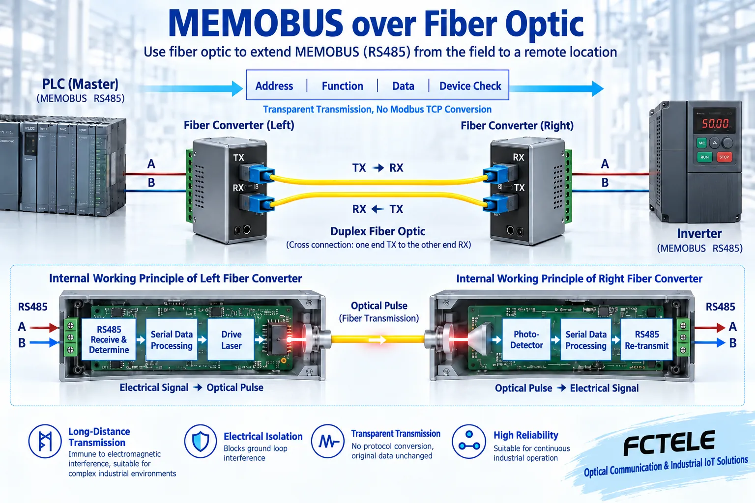
Transparent extension changes the signal path
A common RS485 fiber extension solution uses corresponding transceiver circuits at the near end to receive differential electrical signals and send the recognized digital states to the optical transmitter; the optical pulses travel through the fiber cable to the far end, where an optical receiver and serial driver restore them to electrical interface signals. The reverse direction uses a matching path to complete the response. It extends the physical link and does not automatically change application messages into new commands.
A transparent device should, within its supported conditions, preserve the relevant bytes and necessary timing relationships, but transparency does not mean there is no delay, nor does it mean that incorrectly entered messages will be repaired. The address, function, and data sent by the master still need to be correctly understood by the slave, and the original protocol’s checksum and exception responses still apply. If the two ends originally used different register meanings, simple electrical-to-optical conversion cannot make them understand each other.
It is different from a Modbus TCP gateway
A transparent serial fiber modem usually still carries matching serial services at both ends, with the optical port connecting to the corresponding device; a Modbus RTU-to-TCP gateway, however, needs to handle different message organization, sessions, and request mapping on the two sides. When access via Ethernet is required, it should be clear whether a serial server’s byte transport method or an application gateway’s protocol conversion method is being used, and the two cannot be interchanged based on name alone.
The fact that digital data is transmitted over the fiber link does not prove that it can be directly connected to an ordinary Ethernet switch. The optical port interface, rate, frame or line coding, and paired device all need to be verified. The same optical connector does not guarantee universal interconnection. When multiple serial ports are needed, especially confirm how each channel corresponds to the far end, and do not mistake multiple stations on one bus for multiple independent service channels.
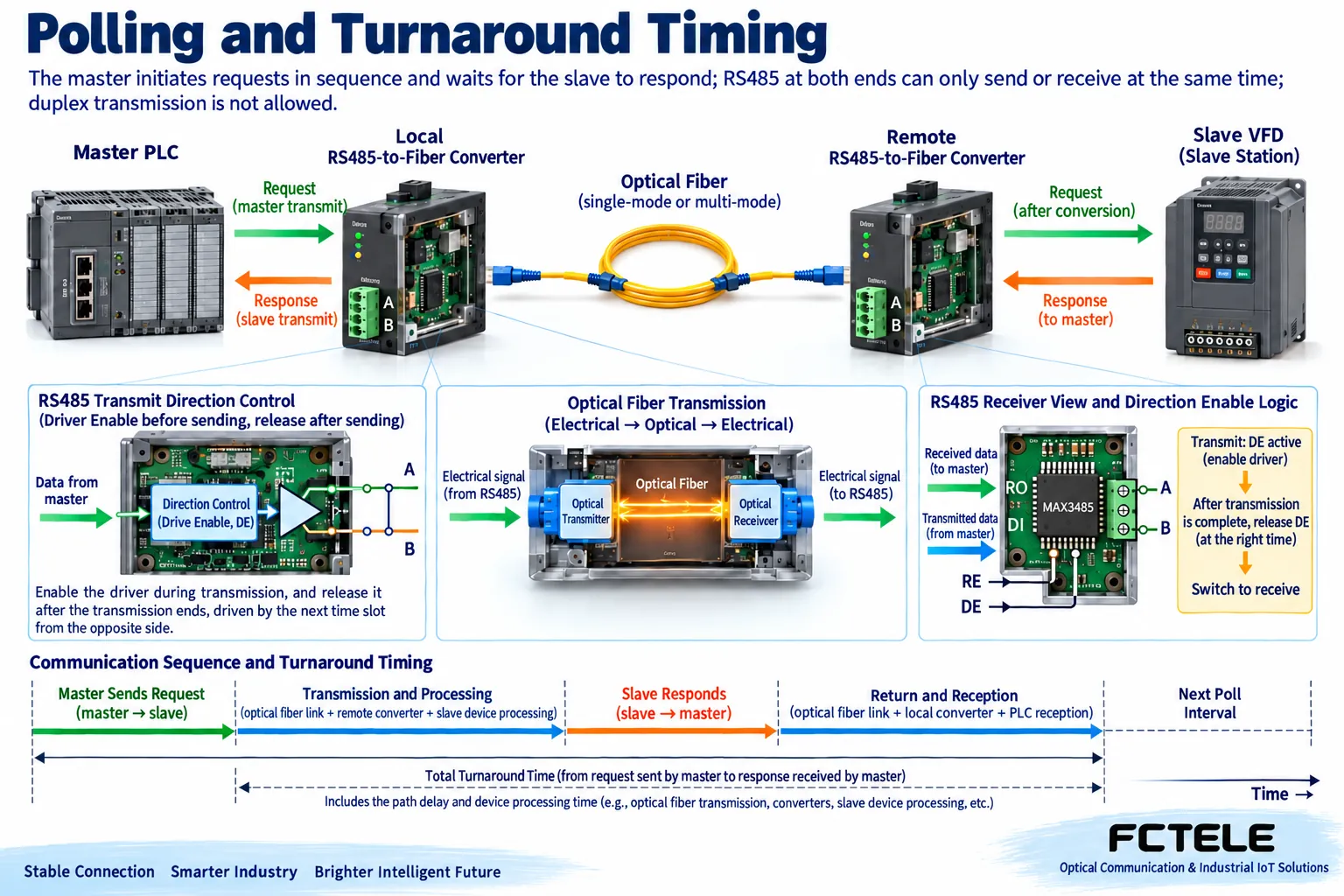
Why two-wire half-duplex needs turnaround time
A common two-wire RS485 link completes requests and responses by taking turns driving. After the master sends, it should release the corresponding line, and the slave processes and returns according to the protocol; the converter’s direction control must also adapt to this process. After adding fiber, propagation, device processing, and direction switching may all increase time, and the original minimum turnaround cannot be assumed to still be suitable based on zero-delay advertising.
The master timeout should cover the complete path, slave processing, and normal response time, and should not be measured only with an idle round trip. Multiple slaves still work according to address and polling rules; on the same ordinary transparent network, adding multiple optical nodes does not allow multiple uncoordinated masters to access simultaneously. Protocol broadcasts and whether responses are required must also be verified according to device specifications to avoid conflicts caused by simultaneous responses.
You can first test a read-only request to one slave, then add a second slave, and record the master’s complete polling time for one round. As nodes increase, waiting, retries, and processing by each device accumulate; even if the optical path itself has margin, the control system refresh cycle may no longer meet requirements. Optimization should start from the actual number of requests, parameters, and error sources, and communication instability should not be simply attributed to insufficient fiber bandwidth.
Check format, copper wiring, and optical port separately
First write down the baud rate, data bits, parity, stop bits, and flow control conditions on both sides. Devices that can automatically detect certain parameters also have supported ranges, which does not mean unknown formats can be connected arbitrarily. The first and last bytes of a request, character intervals, and checksum errors are worth observing, especially for the shortest response and continuous polling; looking only at the transmit indicator light cannot prove the message is complete.
On the copper side, verify A/B definitions, termination, bias, stubs, and reference connections for each electrical segment, and use the manual as the authority for naming and positive/negative conventions. On the optical side, verify fiber type, wavelength, interface, dual-fiber TX/RX or single-fiber pairing, and optical budget. External fiber can prevent the two ends from being directly conductive through this data medium, but power, other copper wires, grounding, and port protection still require complete design, and it cannot be promised to protect against all lightning strikes.
Verify models with Feichang Technology serial products
In the Feichang Technology serial and fieldbus product categories, the document for the numbered 611 FCP-D8G/R8G/Q8G industrial rail-mounted serial fiber modem lists different channel configurations for RS232, RS422, and RS485, and can serve as a basis for selecting serial fiber extension. When using MEMOBUS devices, you should still submit the actual protocol mode, rate, character format, polling, and minimum response requirements, and ask the supplier to confirm whether the corresponding serial version can transparently support them.
The independent channels, number of optical ports, and network topology described on the page should be verified according to the specific ordered version; support conditions for one RS485 path do not mean all interfaces have the same direction control. This product is not claimed here to be a protocol gateway that automatically recognizes all MEMOBUS commands, nor are 4 Mbps, isolation withstand voltage, or certification figures transferred from the old article. When cascading is required, the timing and fault scope after passing through multiple nodes should also be confirmed.
From single-device testing to the complete site
First keep a set of records of the original normal short-line communication, then add a matched pair of optical devices and a short patch cord, and compare the complete response to the same read-only request. After confirming the bytes, returned data, and timing, connect the formal fiber cable, and finally gradually increase nodes and polling load. Change only one condition at a time, so faults can be assigned to copper wiring, optical path, direction control, or the application.
Acceptance should not only record the number of successful communications, but also cover the longest request, shortest response, continuous polling, reconnection after disconnection, and power recovery within the allowed window. Writing critical control or drive parameters should be done according to site management rules, and dangerous actions should not be used to test communication. Save model versions, port correspondence, character formats, optical pairing, request-response, and timeout records to prove that the fiber extension has not disrupted actual device communication.
Documentation note: The principle diagrams are used to explain general mechanisms and are not product photos or measured records. Specific interfaces, modes, and capabilities are subject to the selected model, version, and site verification.
Verification references: Yaskawa MEMOBUS/Modbus communication specifications
Yaskawa MEMOBUS and Modbus differences
TI RS485 design guide
Feichang Technology industrial rail-mounted serial fiber modem
Feichang Technology serial and fieldbus product categories
Related technical topics: How to distinguish switch stacking and cascading: logical devices, uplink capacity, and fault boundaries How to access SDH MSTP multi-service platforms: service mapping, interfaces, and clock verification How to distinguish E1, channelized E1, and PRI: time slots, signaling, and access acceptance
Translated from the Chinese technical article. Source first published: 2021-05-08. Source last revised: 2026-10-13. Read the Chinese source
