


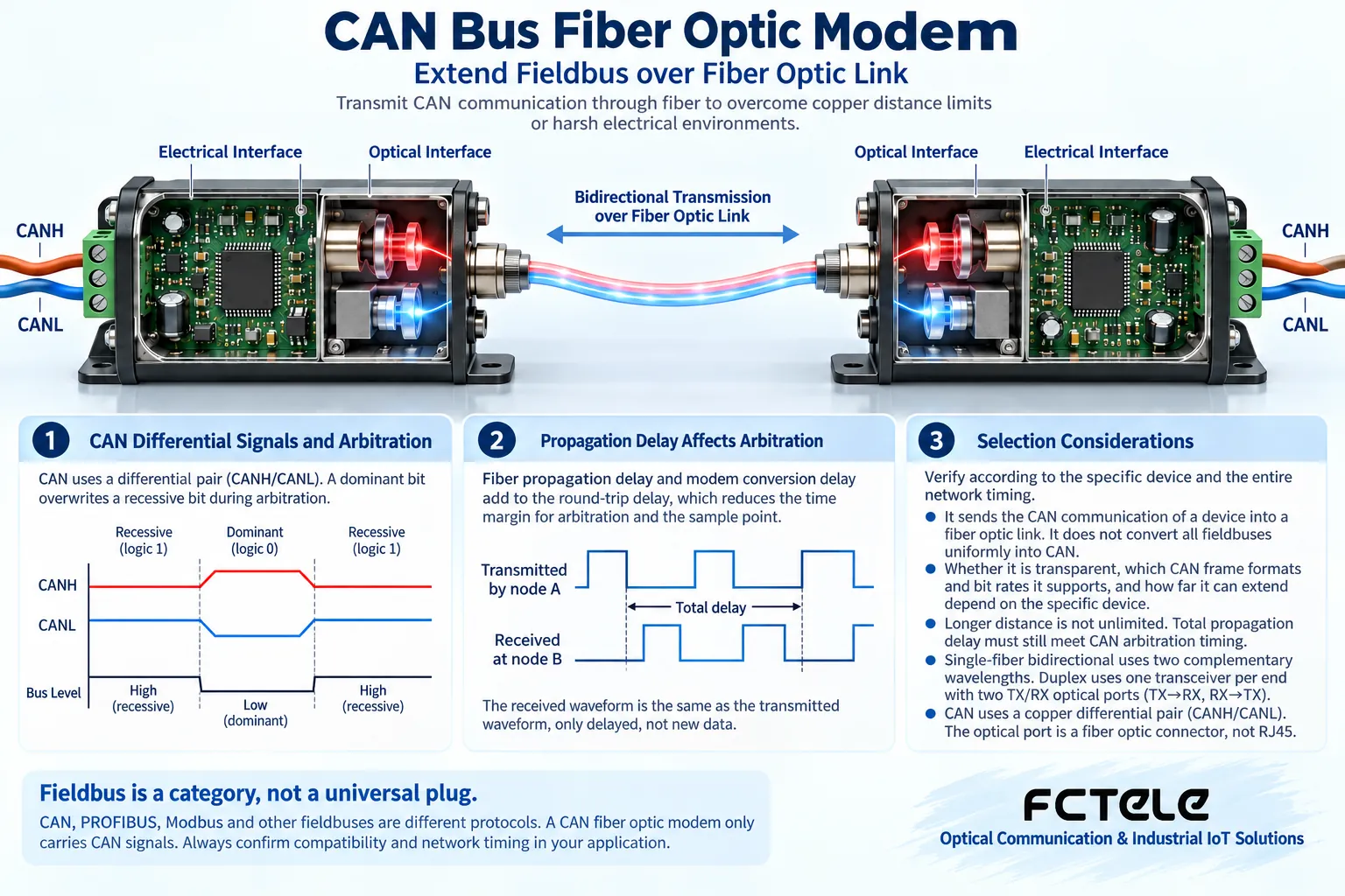
A CAN fiber optic modem sends the CAN communication supported by a device into a fiber optic link, helping it cross copper cable distance limits or electrical environment limits. It does not convert all fieldbuses uniformly into CAN, and it cannot ignore the requirements that CAN arbitration places on propagation delay. Whether it is transparent, what frame formats and rates it supports, and how far it can extend must be verified according to the specific device and the timing of the entire network.
Fieldbus is a category, not a universal plug
CAN, Profibus, Modbus serial communication, and others may all appear in industrial sites, but they use different physical and protocol mechanisms. You cannot assume they can communicate directly just because their names all contain the word bus. CAN uses differential signals, and multiple nodes share the bus; upper-layer applications may also use CANopen or other conventions. A fiber optic modem supports CAN physical transmission, which does not automatically mean it supports all upper-layer management, diagnostics, or protocol conversion functions.
Why arbitration ties distance to rate
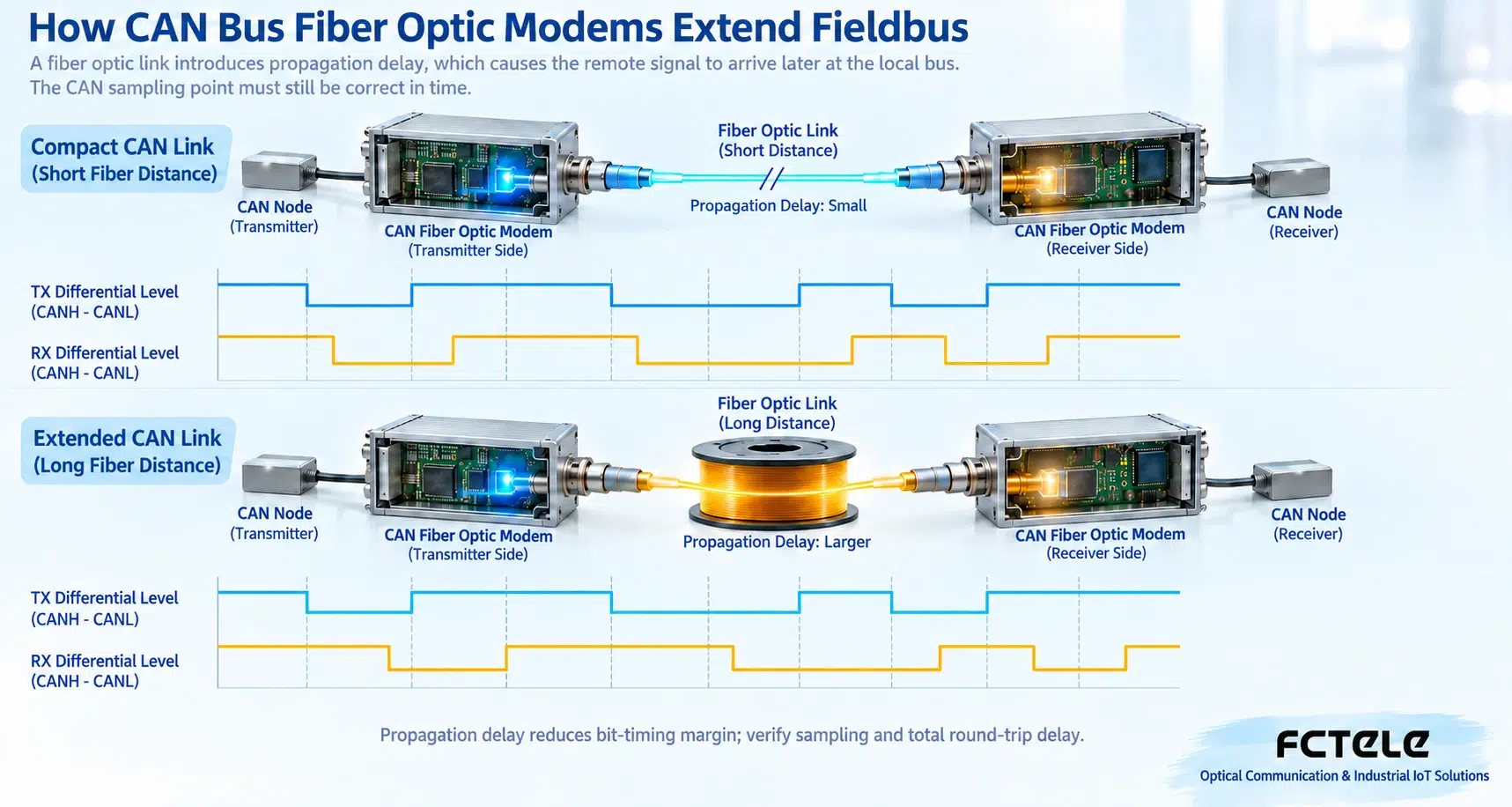
When a CAN node transmits, it also observes the bus, using dominant and recessive states for arbitration. The path over which a signal travels from the local node to the far end and back, affecting the decision, takes time, and cables, transceivers, and fiber optic modems all add delay. The shorter the bit time, the tighter the propagation time that can be accommodated, so distance and rate cannot be promised independently. Low fiber optic transmission loss does not mean propagation delay disappears, nor does it mean the original rate can still be maintained after unlimited extension.
Distinguish transparent extension from gateway retransmission
A transparent optical repeater needs to handle bus states and timing; a gateway may first receive a complete frame and then send it on the other side. The latter changes network behavior and delay and may not be equivalent to one continuous CAN bus. Ring, star, or multi-drop structures also require specific support, and you cannot connect arbitrary optical interfaces into a ring and expect automatic arbitration to work correctly. When choosing, require an explanation of the working mechanism, fault isolation, and frame forwarding conditions, rather than only a maximum distance.
The copper cables on both sides still need correct electrical design
The fiber optic segment cannot replace the termination, wire order, and topology requirements of the CAN copper cable segments. How each electrical segment is terminated depends on the device structure and network design, and it should be configured according to the manual to avoid adding extra terminations and causing excessive load. Check CAN classic frames or CAN FD, baud rate, sample point, interface pins, isolation, and power supply. Industrial terminals with similar appearance do not guarantee the same signal definitions, and you cannot guess CANH and CANL by color.
Accept with actual load and error states
First establish a baseline at small scale and short distance, then add the formal optical path and nodes. Observe error frames, retransmissions, bus-off, and delay, not just whether a message can occasionally be received. Test multiple nodes competing to transmit, continuous load, and recovery after an optical path interruption, and check the alarm and recovery mechanisms. When selecting a manufacturer, compare protocol descriptions, timing parameters, environmental verification, and support capability; do not replace technical conditions with general brand reviews.
Example: low-load testing passes, but retransmission appears at full load
First confirm whether the device is a transparent repeater or a gateway that receives and then retransmits, and compare the rate and configuration of the two electrical segments. Check the optical link delay, queuing and buffering capability, error states, and recovery strategy. A advertised microsecond-level delay does not directly prove that all upper-layer protocols and high loads are compatible, and the maximum frame rate also requires a clear message length and test conditions. Accept with representative nodes and message combinations, and record behavior during competing transmissions; if different baud rates are needed on the two sides, choose a product that explicitly supports this bridging method, and do not treat it as a completely transparent physical bus.
Principle reference:Official technical materials. The structural illustration in this article does not represent specific product specifications; selection should verify the model manual.
Translated from the Chinese technical article. Source first published: 2020-01-13. Source last revised: 2026-10-13T22:21:36+08:00. Read the Chinese source
