


A set of equipment connects the sound interface and the E1 circuit
A mixing console output in a recording studio or broadcast station is an audio signal, while the existing transmission network may only deliver one E1 digital circuit. The two cannot be directly interconnected with a single adapter cable: the sending end needs to convert and organize the sound into transmittable data, and the receiving end then restores the sound. An E1 stereo audio codec handles these two processes, and is used to send a program source to a remote broadcast, monitoring or subsequent processing device.
The FCA-E1A1-X from the Feichang Technology product center, named E1 to one channel stereo audio XLR codec, indicates that one E1 channel can carry one bidirectional stereo channel. Here one stereo channel includes left and right mono channels; bidirectional means that while A sends to B, B can also send its own sound back to A. The number and direction of interfaces should be confirmed according to the ordered version, and one channel cannot be understood as having only one audio plug.
XLR balanced input: first distinguish left and right, and positive and negative
The left and right channels carry different audio content; a balanced analog line uses a pair of signal conductors to represent the same channel, and the receiving circuit reads the difference between the two. The two signal wires of a three-pin XLR are not the left channel and the right channel, and the left and right outputs of a stereo headphone cannot be directly treated as one balanced line input. First confirm the interface definitions of the audio source output and the codec input, connect L and R separately, and handle shielding according to the manual.
XLR is only a connector form; both analog audio and AES/EBU digital audio may use it, yet they carry different electrical signals. Microphones, line outputs and power amplifier speaker outputs also have different levels. The audio source icon in this article’s illustration only indicates the sound source; in practice, a suitable preamplifier or mixing device should provide a matching input. When the product has no clear phantom power and microphone gain information, it cannot be assumed that any microphone can be connected directly.
From continuous voltage to serial data, then back to sound
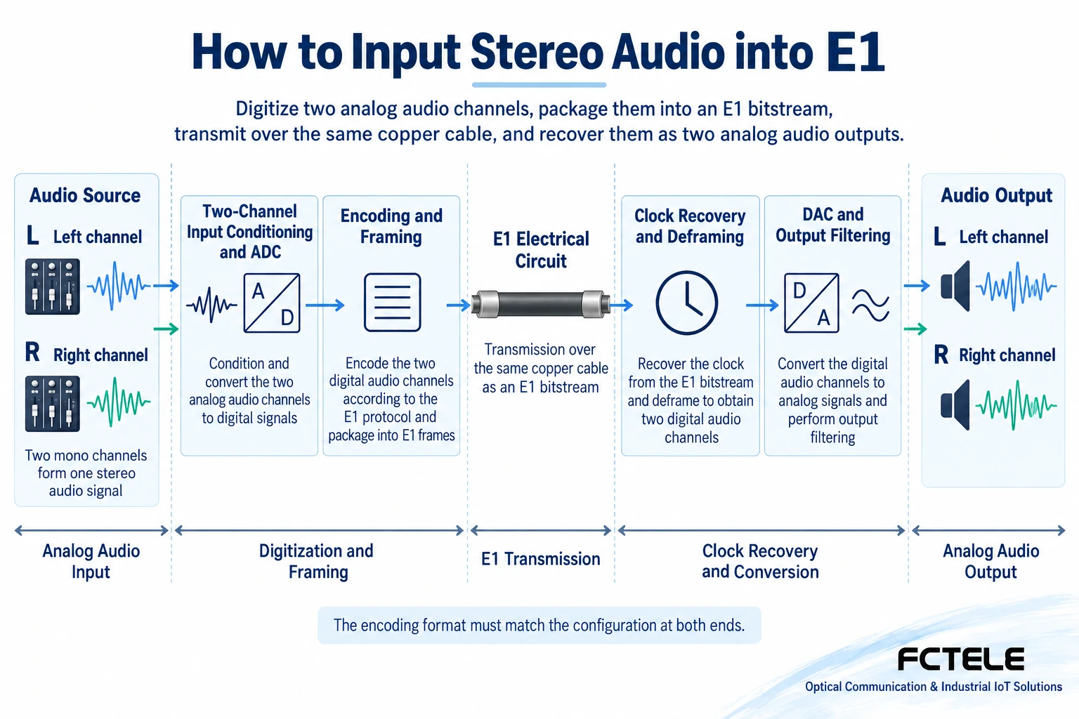
The sending end first performs the necessary level adaptation and filtering on the analog input, then an analog-to-digital converter ADC reads the voltage at instants to obtain digital samples. The left and right channel samples undergo the encoding and framing specified by the device, forming a serial data stream sent to the E1 interface. Framing can be understood as arranging the data according to rules the receiving end recognizes, so that the far end can identify the channel and content; it is not connecting the analog sound as-is to the E1 line.
The receiving end recovers timing from the input bitstream, deframes and decodes according to the matching rules, and then restores the analog sound through a digital-to-analog converter DAC and output filtering. Clock recovery is used to determine when to read data, and cannot repair clipping, noise floor or distortion that occurred before transmission. The product information does not disclose the specific audio coding algorithm, so it cannot be arbitrarily written as using AAC, some compression format, or guaranteeing sample-by-sample losslessness; the models and service configurations at both ends must match.
Bidirectional communication requires connecting E1 transmit and receive correctly
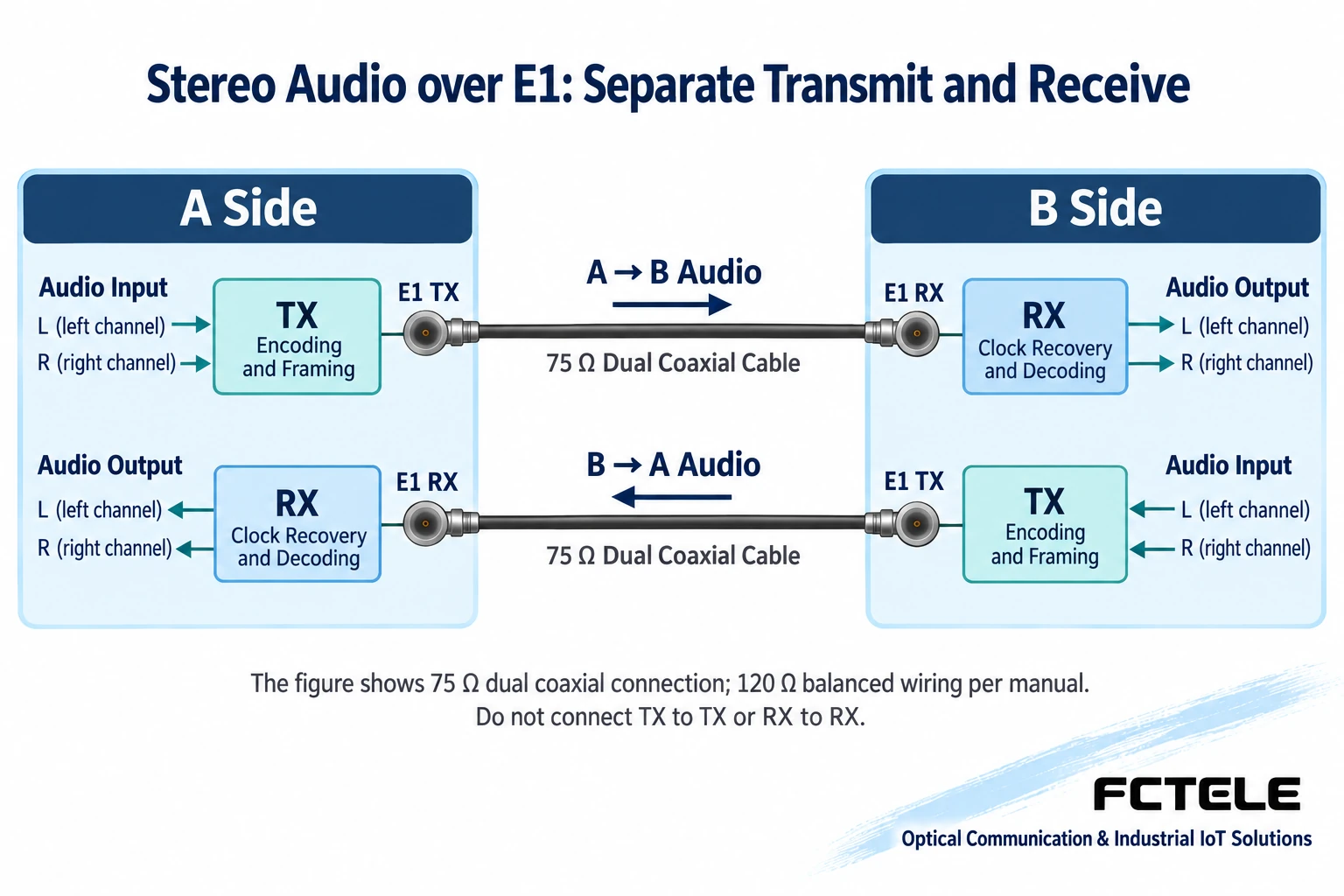
The E1 electrical interface has transmit and receive directions. Using a 75Ω unbalanced coaxial interface as a teaching example, end A TX connects to end B RX, and end B TX connects to end A RX; a bidirectional link uses two corresponding coaxial paths. Each direction can carry its own left and right channels, and the two ends are not required to play the same program. When wiring, first identify the ports and directions, to avoid connecting only one direction and then declaring the bidirectional service normal.
The transmit and receive wire pairs and connector definitions of the 120Ω balanced interface must be checked against the delivered equipment manual; using a plug similar to a network cable does not mean it can be connected to an Ethernet switch. Conversion between 75Ω and 120Ω requires a suitable impedance conversion solution, and cannot be done by changing only the plug. The clock source and mode must also follow the synchronization arrangement of the actual circuit; all devices cannot be set to independent internal clocks and then judged for long-term stability only by indicator lights.
The capacity of a 2M channel is not equal to the ADC bit depth
The nominal line rate of E1 is 2.048 Mbit/s. The audio A/D bit width describes how the conversion stage represents samples, and does not directly indicate that the same bit width and sampling rate are used for transmission in E1. For example, if two mono channels are transmitted uncompressed at 48 kHz and 16 bit, the net sample bit rate alone is 48000 times 16 times 2, equal to 1.536 Mbit/s; the device’s actual framing and other overhead must also be considered. This calculation is a teaching example, not the working configuration of the FCA-E1A1-X.
Likewise, two uncompressed 48 kHz, 24 bit channels already reach 2.304 Mbit/s, exceeding the total rate of one direction of an E1 line, and cannot be directly packed in that way. Whether the device uses a different sampling rate, a different effective bit width or other coding requires support from specific technical information. A bidirectional line should calculate the capacity of each direction separately; the rates of the two directions cannot be added together to prove that one direction is sufficient, and a 24 bit chip label cannot be interpreted as a guarantee of overall sound quality.
Extend through a transmission network, rather than plugging directly into optical fiber
The FCA-E1A1-X information states that the 2M channel of an SDH, PDH or microwave system can be used to achieve point-to-point audio source transmission. This means the intermediate equipment provides a suitable E1 circuit, and the codec is responsible for conversion between audio and E1. The transmission network may contain optical fiber internally, but this E1 device cannot therefore be said to have a general optical port, or the E1 line directly plugged into an ordinary fiber optic transceiver.
The delivered circuit should be checked against G.703 electrical interface, line coding, impedance, timing and framing related agreements, and verify that the required service data can pass correctly. G.703 specifying the electrical interface does not guarantee that two audio codecs use the same audio mapping. When carriage over an IP network is required, a suitable E1 circuit emulation solution should be selected separately and the clock and delay checked; for one-to-many transmission, a suitable E1 distribution device is needed, and multiple receiving ends should not be arbitrarily connected in parallel with coaxial T-connectors.
Check the ordering boundaries against the FCA-E1A1-X information
The product description clearly states XLR balanced audio interfaces, but the connection terminals in the parameter table on the same page say RCA, and some fields lack complete test conditions. The project should be based on the interface diagram, manual and manufacturer confirmation information of the ordered model, and check the analog input and output form, number of channels, level, sampling and actual coding configuration. This article uses the confirmable product positioning and working process, and does not directly treat conflicting table fields as a delivery guarantee.
If the program source already outputs AES/EBU digital audio, the FCA-E1AES1 listed separately in the product center can be compared; it and the analog XLR model cannot be interchanged based only on plug appearance. Power supply options, impedance versions and matching ends should also be written into the order list. Signal-to-noise ratio, bandwidth and distortion should be understood together with the overall test conditions; the units of input attenuation and level cannot be mixed, and chip theoretical specifications certainly cannot be transplanted into product measured conclusions.
Acceptance checks the program, direction and continuous operation at the same time
First use a matching audio source and downstream equipment to set up a short circuit test, control the input level and monitoring volume, provide distinguishable different content to the left and right channels respectively, and confirm that the far end has no channel swap, missing sound or clipping. Then send another set of content in the reverse direction to verify the input and output directions at both ends. For test sound quality, record the input level, frequency, output load and measurement bandwidth; listening is used to judge obvious phenomena and does not replace instrument measurement under specified conditions.
After connecting to the installed E1 transmission circuit, observe whether there are loss of lock, alarms, intermittent audio breaks and abnormalities during long-term operation, and verify recovery after disconnection and power cycling according to the maintenance arrangement. Delay must have its measurement points defined and include actual audio processing and intermediate carriage; a fixed product delay cannot be calculated directly from the E1 rate. The delivery record should include the models at both ends, wiring diagram, clock source, coding agreement and test results, so that later expansion and fault location have a reusable basis.
Information note: the principle diagrams have been checked for technical content and are used to explain general mechanisms; they are not product photos or measured records. Specific interfaces, modes and capabilities are subject to the selected model, version and on-site verification.
Verification materials:Feichang FCA-E1A1-X product information
Feichang E1 video and audio codec category
Feichang FCA-E1AES1 digital audio model
ITU-T G.703 digital interface specification
ITU-T G.704 digital frame structure specification
Translated from the Chinese technical article. Source first published: 2019-12-25. Source last revised: 2026-10-13T11:40:22+08:00. Read the Chinese source
