


First understand the line standard, then decide the conversion direction
E1 and T1 are both traditional line systems that continuously transmit digital information, and they are often used for voice and leased line services. When one end is E1 and the other end is T1, you cannot just change the plug, and you cannot assume that buying a device labeled “E1 protocol converter” will let them communicate directly. The two differ in line rate, frame structure, electrical conditions, and service organization.
When selecting equipment, first write down clearly what needs to be preserved: the raw bitstream of the entire line, some voice channels, or a certain data service. A device being able to select E1 or T1 port mode only means it supports the corresponding line interface; to truly map services between different standards, the corresponding gateway function is also needed. Similar names are not evidence of interoperability.
Same frame period, why are the rates different?
A typical framed E1 has thirty-two time slots per frame, each time slot has eight bits, and one frame has two hundred fifty-six bits in total. At eight thousand frames per second, the line rate is therefore 2.048 Mbit/s; one frame period is one hundred twenty-five microseconds. Here, a time slot is a periodically assigned position, not an extra physical wire.
A typical basic T1 frame contains twenty-four eight-bit channels and one frame alignment bit, for a total of one hundred ninety-three bits. It also has eight thousand frames per second, and the line rate is 1.544 Mbit/s. That one bit is frame overhead, cannot be counted as an eight-bit service channel, and one hundred ninety-three bits cannot be called one hundred ninety-three time slots. The same frame period on both lines comes from the basic beat of eight thousand times per second; the different number of bits within the frame is what creates the different line rates.
Service capacity cannot be compared only by total line rate
E1 TS0 is used for overhead such as frame alignment, and TS16 has corresponding uses in modes such as channel-associated signaling, so it cannot be assigned to user data in all scenarios. A common voice configuration has thirty service channels, but “thirty voice channels” cannot be applied to any framed or unframed E1 device. Partial time-slot data, full-line transparent transmission, and different signaling configurations each have their own capacity boundaries.
T1’s twenty-four channels also need to be understood together with the frame, signaling, and application mode. Channel-associated signaling may use corresponding bits within service channels, so some data services are therefore limited; exactly how it is organized must be confirmed according to the mode used. What customers care about is how many services can be carried and what information each service retains, not simply comparing the two numbers 2.048 and 1.544.
Suppose thirty E1 voice channels all need to be sent to a T1 end that has only twenty-four corresponding channels. They cannot all fit without changing the plan. Services can be redistributed, additional bearer capacity can be added, or a suitable gateway can be used, but it must be made clear how the missing capacity will be solved. Conversion does not create positions that do not exist in the line.
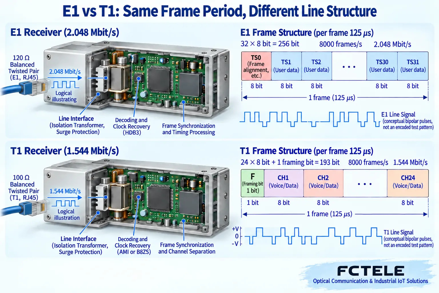
Interface, coding, and signaling are problems at different layers
G.703 describes the physical electrical conditions of digital interfaces, and G.704 describes the related synchronous frame structure. E1 commonly uses seventy-five ohm unbalanced coaxial and one hundred twenty ohm balanced interfaces, while T1 commonly uses one hundred ohm balanced interfaces; the actual ports, cables, and termination conditions should still be confirmed according to the device version. The appearance of RJ45 on both housings does not mean the pins, levels, and impedance are the same.
Line coding arranges pulses to represent bits and helps the receiving circuit recover data and clock. E1 commonly uses HDB3, while T1 commonly uses choices such as AMI or B8ZS, and the configuration from the other end cannot simply be reused. Frame alignment is the process of finding frame boundaries in the bitstream; signaling describes call or channel status. The line waveform being receivable does not mean the frame and service signaling are already compatible.
Across voice systems, channel-associated or common-channel signaling, numbers, and call state handling may also be involved. An E1 interface gateway does not necessarily have voice codec, number conversion, or SIP functions. During procurement, interface adaptation, channel mapping, and call protocols should be listed separately to avoid grouping all three tasks under one name, “protocol conversion.”
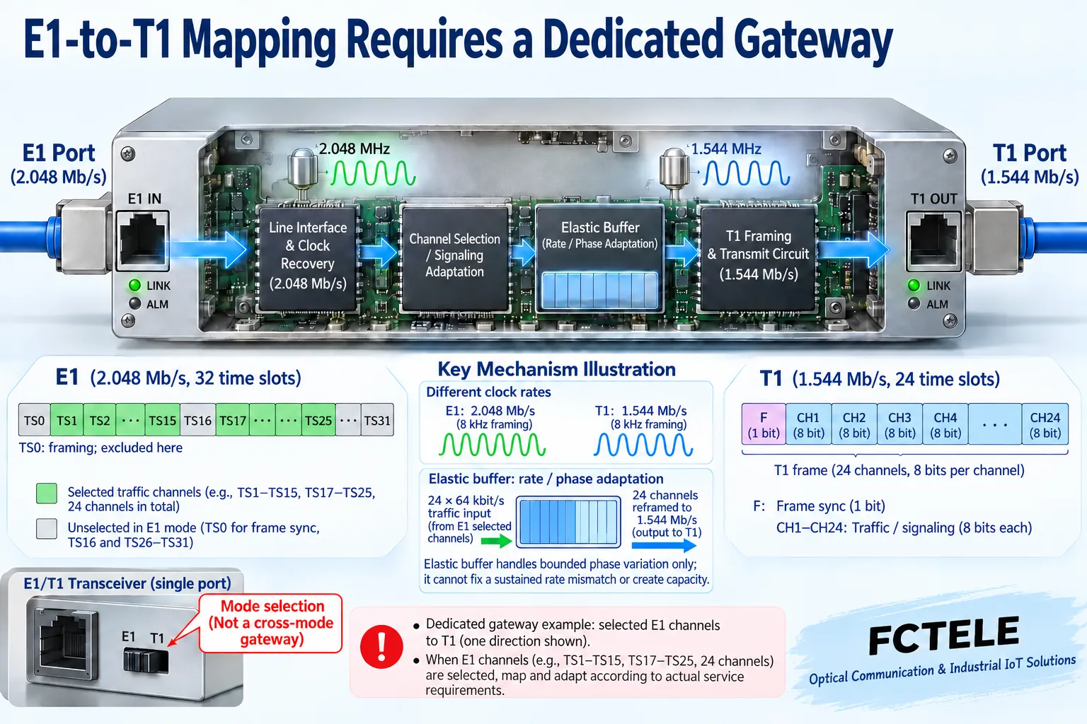
Dual-mode ports and cross-standard gateways: where is the difference?
Using public information for the Analog Devices DS2155 as an example, the same transceiver chip can select T1, E1, or J1 operating mode in software and includes circuits such as line receive and frame processing. This makes it convenient for equipment design to support multiple interfaces, but a single port selecting one mode does not mean it simultaneously converts E1 input into T1 output. This is a chip mechanism example and does not prove that any Feichang Technology product uses this chip.
True cross-standard adaptation requires at least clarifying how line processing at both ends, service channel extraction and reassembly, timing, and signaling correspond. If only selected sixty-four kilobit channels are used, the system can reorganize the corresponding services within its capability; if the entire raw E1 bitstream is required to enter one T1 completely transparently, the input rate is already higher than the output line rate, and buffering alone cannot sustain it over the long term.
Elastic buffering can handle limited phase or short-term beat differences, but it cannot eliminate continuous capacity shortage. Whether a given gateway supports the required mapping, independent clock domains, signaling adaptation, and fallback output on failure requires specific information and testing between both ends. Do not treat the abbreviation “supports E1/T1” as a guarantee of all conversion capabilities.
Feichang Technology’s existing E1 converters should be selected according to the real interface
The Feichang Technology official website divides E1 to V.35/V.24, Ethernet to E1, and circuit emulation into different series. E1 to V.35 adapts a synchronous serial data interface, Ethernet to E1 lets network frames use an E1 channel, and E1 over IP lets the original E1 circuit pass through a packet network. They may all have an E1 port, but they are not equal to an E1/T1 cross-standard gateway.
The Feichang Technology E1-related categories and details checked in this article cannot be used as evidence that T1 conversion is already supported. If a project really has T1 equipment, the supplier should be provided with the line standard, framing and signaling requirements, number of service channels, and timing relationships so the corresponding model and version can be confirmed. The port used cannot be inferred just because an enterprise is located in Europe, Asia, or North America; the final basis should be the equipment and line documentation.
Commissioning and acceptance: prove interoperability in three layers
The first layer verifies electrical reception and line alarms, the second layer verifies frames, channels, and clocking, and the third layer verifies real services. Within the maintenance window, use suitable test equipment to check errors and slips, confirm the mapping channel by channel, and then verify bidirectional data or call procedures. Signaling needs to be tested together; hearing sound once is not enough to conclude that all voice channels and service states are correct.
Acceptance records should include the standard and mode at each end, the mapping table, clock source, test duration, and failure recovery behavior. If the transformation goal is only to let E1 run over fiber or IP, evaluate it first according to the corresponding bearer solution; only when the remote service itself requires T1 should the discussion move to cross-standard adaptation. Only after clearly explaining the services to be preserved can the required equipment and the actual boundaries of conversion be judged.
Documentation note: The principle diagrams have been checked against technical content and are used to explain general mechanisms; they are not product photos or measured records. Specific interfaces, modes, and capabilities are subject to the selected model, version, and on-site verification.
Reference materials: ITU-T G.703: Electrical characteristics of digital interfaces
ITU-T G.704: E1 and T1 frame structures
Analog Devices DS2155: Line receive, alarm, and loopback mechanisms
E1 converter categories and selection
Feichang Technology E1 to V.35/V.24 series
Translated from the Chinese technical article. Source first published: 2024-03-27. Source last revised: 2026-10-13T13:46:37+08:00. Read the Chinese source
