


A device has not lost its network connection, yet its first frame after an idle period may arrive a little later than the frames that follow. One factor worth checking is port power saving. Energy Efficient Ethernet, or EEE, allows a compatible port to reduce some electrical activity while there is no traffic, then resume when data arrives. This sleep does not mean switching off the whole industrial switch. Understanding the wake-up process helps us evaluate energy saving alongside control requirements.
Why does an idle network port still use power?
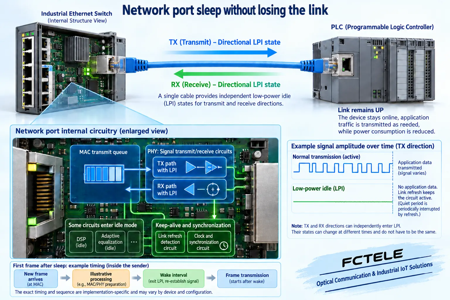
After a cable establishes a link, its endpoints do more than wait for file transfers. They encode, transmit and receive electrical signals and maintain an identifiable connection. The PHY is the physical-layer transceiver circuit: it turns internal data into cable signals and converts received signals back into data. The MAC manages Ethernet frame transmission and reception. A frame is one unit of data sent over Ethernet. These functions have different responsibilities; a port is more than a simple on-off switch.
In its normal operating state, an interface may continue producing normal idle signaling and running associated circuits even when the application has nothing to send. EEE reduces activity in parts that can enter a lower-power state. Support, eligible speeds and the circuits affected depend on the actual hardware and firmware. This explanation uses a compatible full-duplex twisted-pair link. It does not claim that every optical port or industrial switch supports the same mechanism.
Both endpoints must agree before using low-power idle
Low-power idle, abbreviated LPI, is the mechanism EEE uses. When the link is established, compatible endpoints exchange capabilities to determine whether an appropriate EEE mode can operate. Checking a local energy-saving box does not prove that the feature is operational. The partner may not support it, the current speed may be unsuitable, or the driver may leave it disabled.
Think of two people agreeing on when to rest and how to resume their conversation. This analogy explains coordination only. The real indication is carried by specific physical-layer signaling, rather than an application message saying that a device is going to sleep. Full duplex means that data can travel in both directions at the same time. Transmit-direction states should be considered separately; one idle direction does not mean that both devices have powered down completely.
Quiet periods and refresh serve different purposes
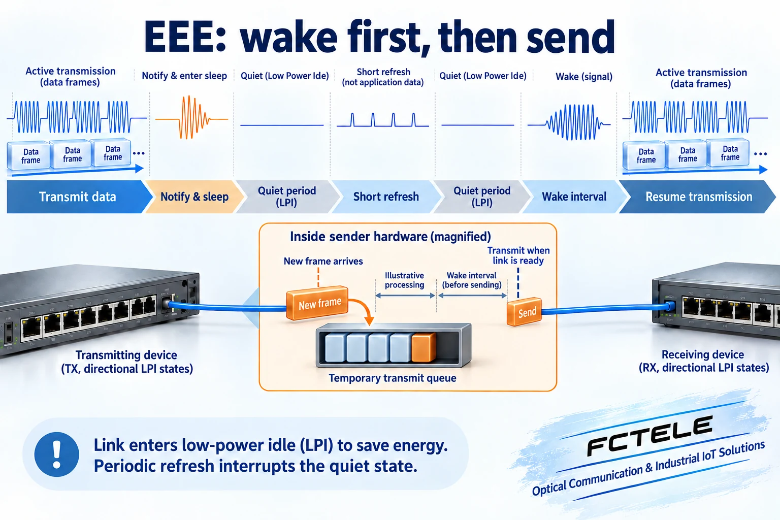
When the implementation permits sleep and no data needs transmission, the sending direction indicates entry into LPI, completes a sleep transition and enters a quiet period. Parts of the transceiver reduce their activity, creating an opportunity to save power. Brief refresh activity interrupts the quiet period. Refresh helps maintain the link and synchronization conditions the receiver needs to continue operating according to the agreed behavior.
Refresh signaling is not a PLC data report or a forwarded application frame. Packet-capture software normally observes frames, so an empty capture window does not prove that the physical layer has produced no signal. A normal EEE idle state retains the established link. Repeated UP/DOWN events still require investigation of cabling, power, drivers and interoperability; energy saving is not a blanket explanation for unstable links.
A newly arrived frame may need to wait for wake-up
When a frame arrives while the transmit direction is idle, the endpoint starts the wake-up process. Relevant circuits resume operation, and the receiving endpoint gets ready to recognize normal signaling before data transmission begins. The frame waits in a transmit queue during the necessary interval. That queue is inside the device; the frame is not parked halfway along the cable.
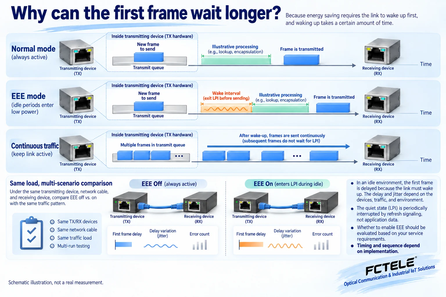
The first frame after an idle interval can therefore experience additional waiting compared with an already active port. Once traffic continues, later frames do not necessarily repeat a complete sleep-and-wake sequence individually. The actual delay depends on the link type, implementation and policy. A single microsecond value cannot describe every device. Some implementations may also accumulate frames before transmission. Such coalescing can extend the waiting period, but it should not be assumed to exist on every port.
What does this mean for industrial control?
Consider a hypothetical PLC sending periodic small frames to a monitoring application that otherwise has little traffic. If gaps allow relevant ports to re-enter idle, each return to active operation may change the arrival time. This example illustrates a possibility; it is not an FCTEL measurement. A continuous file upload may run smoothly while intermittent control traffic has different timing, because the two loads keep ports in different states.
First-frame delay describes the waiting experienced by the first frame following an idle period. Delay variation describes how arrival timing changes between frames. A small additional wait may be acceptable for occasional status readings. Tightly timed control tasks need it assessed against their cycle, timeout and error allowance. EEE idle does not by itself prove packet loss, nor does it imply that EEE must always be disabled. The decision needs evidence from the particular link.
How to check the port and run a fair comparison
Record the switch port, partner network adapter or controller, firmware and driver versions, negotiated speed and actual EEE operating status. Supported, enabled and successfully negotiated are three different states. Keep them distinct in screenshots. If the device provides LPI entry counts, residence time or wake-up error statistics, correlate them with application activity. Do not invent idle counts when the device supplies no such statistics.
During an approved maintenance window, compare EEE enabled and disabled using the same port, cable and application load. Include continuous traffic, the first frame after idle, periodic small frames and mixed bursts. Repeat the comparison rather than relying on one ping. Change one condition at a time and record maximum waiting, timing variation, application timeouts, frame errors and link flaps. State the measurement tool accuracy and capture location; host scheduling delay can otherwise be mistaken for port wake-up.
If disabling EEE improves the result, restore the original setting and repeat the test to establish reproducibility. Check official documentation and the compatibility of both endpoint versions. If the issue remains, investigate congestion, CPU load, application scheduling and cable quality. A mirrored-frame timestamp does not necessarily identify the instant the original first bit entered the wire. Ordinary packet capture should not be presented as a precise PHY wake-up measurement.
Do not confuse EEE with waking a powered-down computer using a special packet or with saving power after a cable is unplugged. These involve different states and controls. A product interface labeled green Ethernet may cover several policies. Read the exact feature name, eligible ports and triggering conditions before deciding what the test has actually changed.
Document support and acceptance conditions
FCTEL provides industrial switch and fiber media-converter documentation. Start with the real product interfaces, speeds and management features, then confirm separately whether EEE is supported, can be disabled and offers observable status. The linked product documentation is a resource for checking an actual product; this article does not claim that the linked model implements EEE. Industrial grade and low power alone do not establish post-idle timing for a control link.
Keep the topology, endpoint models and versions, relevant per-port EEE settings, test loads and results in the handover record. Recheck after replacing an adapter or upgrading firmware because the negotiated combination may change. The principle requires no formula: reduce some circuit activity during idle, use refresh to maintain agreed conditions, and wake before sending new data. Include that waiting in the real application acceptance test.
If a device provides no EEE status or disable option, obtain clarification from its manufacturer before deciding whether it suits a timing-sensitive link. Forcing a different speed is not a valid substitute for disabling EEE in a controlled test: speed itself changes transmission time and negotiation conditions. Preserve the original configuration and document verified options instead of guessing from menu names.
Technical references: Microchip AN2637: EEE and link states; Microchip VSC7420documentation: LPI, refresh and wake; Cisco: EEE negotiation and latency; EEE frame-coalescing research; EEE network delay research; FCTEL Technical Articles; FCTEL industrial switch documentation (Chinese). Original AI-assisted illustrations explain generic principles, not specific product internals or measurements. EEE capability is not asserted for the linked FCTEL model.
