


The key to ERPS configuration is not connecting the fibers into a ring, but establishing the correct protection instance: clearly define the ring ports, RPL role, control VLAN, and protected services, and verify the entire ring configuration before closing the loop. Under normal conditions, services on the protection link are blocked; after a fault, the corresponding block is removed to provide an alternative path for services. The recovery process still needs to be tested in practice, and unconditional zero interruption cannot be promised.
Why a physical ring cannot forward everything
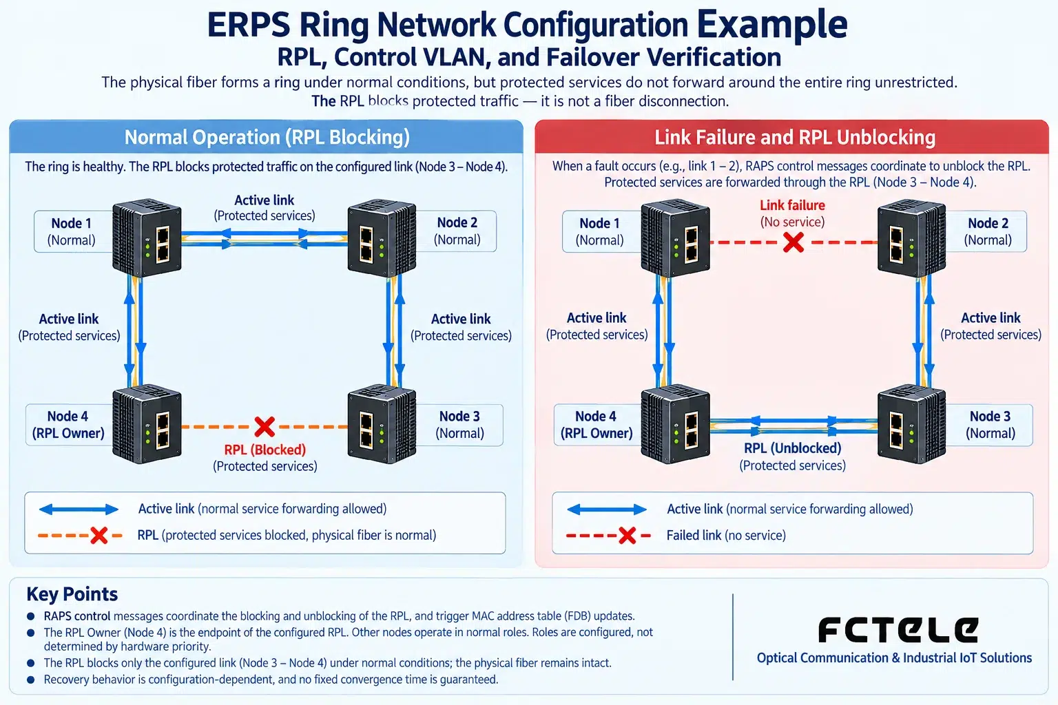
In an ordinary Layer 2 ring, broadcast frames may be copied in a loop. ERPS uses the protection mechanism of ITU-T G.8032 to keep protected services loop-free under normal conditions. The RPL is the ring protection link, not a fiber that must be unplugged; the device controls service forwarding through port states. R-APS control messages are used to convey the relevant protection states.
The RPL Owner is responsible for the corresponding protection control, and its adjacent RPL Neighbor role and the roles of other nodes should be configured according to the device implementation. Roles are not determined by cabinet position, and not all nodes are set as Owner. Protocol version, instance, and VLAN constraints must be checked in the manual for the corresponding model; menu names or default parameters from different brands cannot be copied directly.
A verifiable four-node lab plan
The following uses four switches A, B, C, and D that support compatible ERPS as a teaching example, and does not provide directly executable commands that have not been verified for a specific model. The connection order is A—B—C—D—A, and each switch uses two ring ports. Choose D—A as the RPL, plan A as the Owner and D as the adjacent node, with B and C as ordinary forwarding nodes; the specific role options are subject to the firmware implementation.
Management addresses can be planned as 192.168.50.11 to 14 in an isolated lab network, and it should be confirmed that they do not conflict with existing addresses. These are example addresses, not device default login addresses. The service VLAN can be given as an example of 100, and the control VLAN as an example of 4090, provided that the device allows it, it is not occupied by other functions, and the membership and tagging method are set according to the manual. The control VLAN cannot be used casually as an ordinary terminal service.
Configure on an open chain first, then verify after closing the loop
First leave one link unconnected, establish a management connection to a single device, and back up the original configuration. Create the required VLANs, include the correct ring ports in the corresponding instance, and verify the protected service scope, RPL port, control VLAN, and protocol parameters. Port numbers on each node may differ, so they should not be copied from the same row only; the requirements of different devices for instance numbers must also be verified.
After saving the configuration, first confirm that both services and management are reachable on the open chain, then connect the last link according to the maintenance plan. Check the protocol status, port roles, and RPL blocking status, and confirm that there are no broadcast anomalies or continuous MAC table flapping. If the status does not match expectations, restore the open link and troubleshoot; do not continue to repeatedly close the loop and test by trial and error.
Failover and recovery must be tested separately
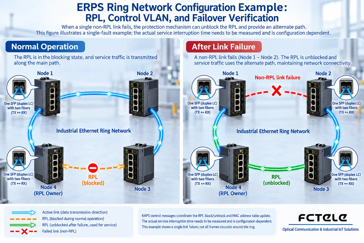
Continuously send test traffic and record the time, then disconnect one non-RPL link in an approved lab environment or maintenance window. Confirm that the fault can be detected, the protection state changes, and the alternative path carries services, and record packet loss, latency, and video interruption. Merely observing port lights or one successful Ping cannot prove that the switching quality meets the requirements.
After reconnecting the link, also check whether it switches back as expected. Parameters such as the revertive mode and wait-to-restore time affect performance and should not be set to the minimum without evaluation. The fault scope may also differ when testing link interruption and node power loss; single-ring protection does not mean that all nodes can still communicate with each other when two points are disconnected at the same time.
Do not omit planning when expanding to dual rings
When two rings share an aggregation device, the ports, protection instances, control messages, and service scope of each ring must be clearly distinguished. The shared device itself may become a common point of failure, and the two rings cannot be equated with two independent systems. Adding VLANs, modifying trunks, or stacking other ring network protocols should all be evaluated for whether they affect the ERPS protected scope.
Only by retaining the topology, port list, configuration backup, software version, and test records can the lab plan be used for engineering. For standard principles, refer to ITU-T G.8032; actual deployment should still be based on the configuration instructions for the corresponding Feichang Technology model and on-site verification.
Translated from the Chinese technical article. Source first published: 2022-10-19. Source last revised: 2026-10-13T23:07:12+08:00. Read the Chinese source
