


Ethernet standards define how Ethernet services are transmitted. T568A/T568B define the termination wire order for common eight-core twisted-pair cables. The two are not standards at the same layer. When making network cables, keep the correct pairs, terminate according to one consistent scheme, and verify wire order and link performance; merely having all eight wires conductive cannot guarantee reliable operation of 100 Mbps, 1000 Mbps, or PoE.
First understand the numbers next to the interface
In 100BASE-TX and 1000BASE-T, the speed and medium meanings differ from wire-order names. 100BASE-TX usually uses two pairs of twisted pair, and 1000BASE-T uses four pairs. Whether a network port can reach the target speed also depends on the devices at both ends, negotiation status, cable category, and overall link quality. It is not determined by whether the RJ45 plug has a metal shell.
Fiber Ethernet has different physical layer standards, and copper cable wire order cannot be applied to optical modules. IEEE 802.3 covers the Ethernet technology system, while cabling standards also specify connection, performance, and installation requirements. In engineering, check both equipment standards and cabling conditions, and do not mix them into a single “wiring mnemonic.”
Why four pairs must stay paired
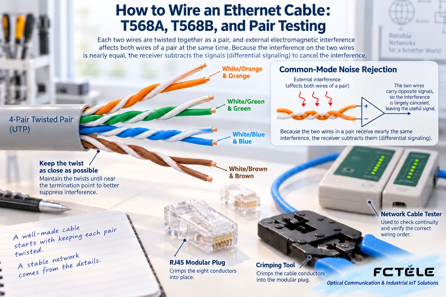
The two conductors in one twisted pair jointly transmit a differential signal, and the twisted structure helps control external interference and coupling between pairs. If two wires from different twisted pairs are combined into one pair, even if a continuity tester lights up wire by wire, severe crosstalk may still occur. This kind of split-pair problem cannot be solved by “changing to a different RJ45 plug shell.”
The exact wire order of T568A and T568B
Read according to pins 1 to 8 as defined by the connector standard: T568A is, in order, white-green, green, white-orange, blue, white-blue, orange, white-brown, brown; T568B is, in order, white-orange, orange, white-green, blue, white-blue, green, white-brown, brown. The two swap the positions of the orange and green pairs, while the positions of the blue and brown pairs remain unchanged.
Before working, confirm the viewing direction of the RJ45 plug and the pin numbering. Do not read the order seen from the back as if it were the front. It is recommended to directly refer to the numbering diagram in the connector or construction specification. Ordinary straight-through patch cords use the same wire order at both ends; historically, using A at one end and B at the other can form a crossover cable suitable for some old two-pair Ethernet interfaces, but it is not a universal crossover scheme for all speeds.
Modern devices may support auto MDI/MDI-X, but this does not allow arbitrary wiring, nor can it correct split pairs, poor contact, or all wire-order errors. Permanent links, patch panels, and patch cords should be implemented according to a unified project specification, and the termination scheme should be clearly recorded.
Details that truly affect quality during termination
Choose connectors that match the cable category, wire gauge, and conductor type. The suitability of solid wire and stranded wire cannot be assumed to be the same. When stripping, avoid damaging the conductors. After arranging the pairs, reduce excessive untwisting, ensure each core enters the correct position, and crimp reliably. The outer jacket should be properly secured to prevent pulling force from acting directly on the conductor connection points.
Shielded systems also require overall connection and suitable grounding design; adding a metal RJ45 plug does not complete it. Cabling routes should avoid inappropriate strong-current interference and mechanical damage; bending, pulling, and installation requirements should be implemented according to cable and cabling specifications. Do not use splicing bare wires, arbitrary extension, or repeated bending as a substitute for standard connections.
The wire-order lights are all on, so why is it still only 100 Mbps?
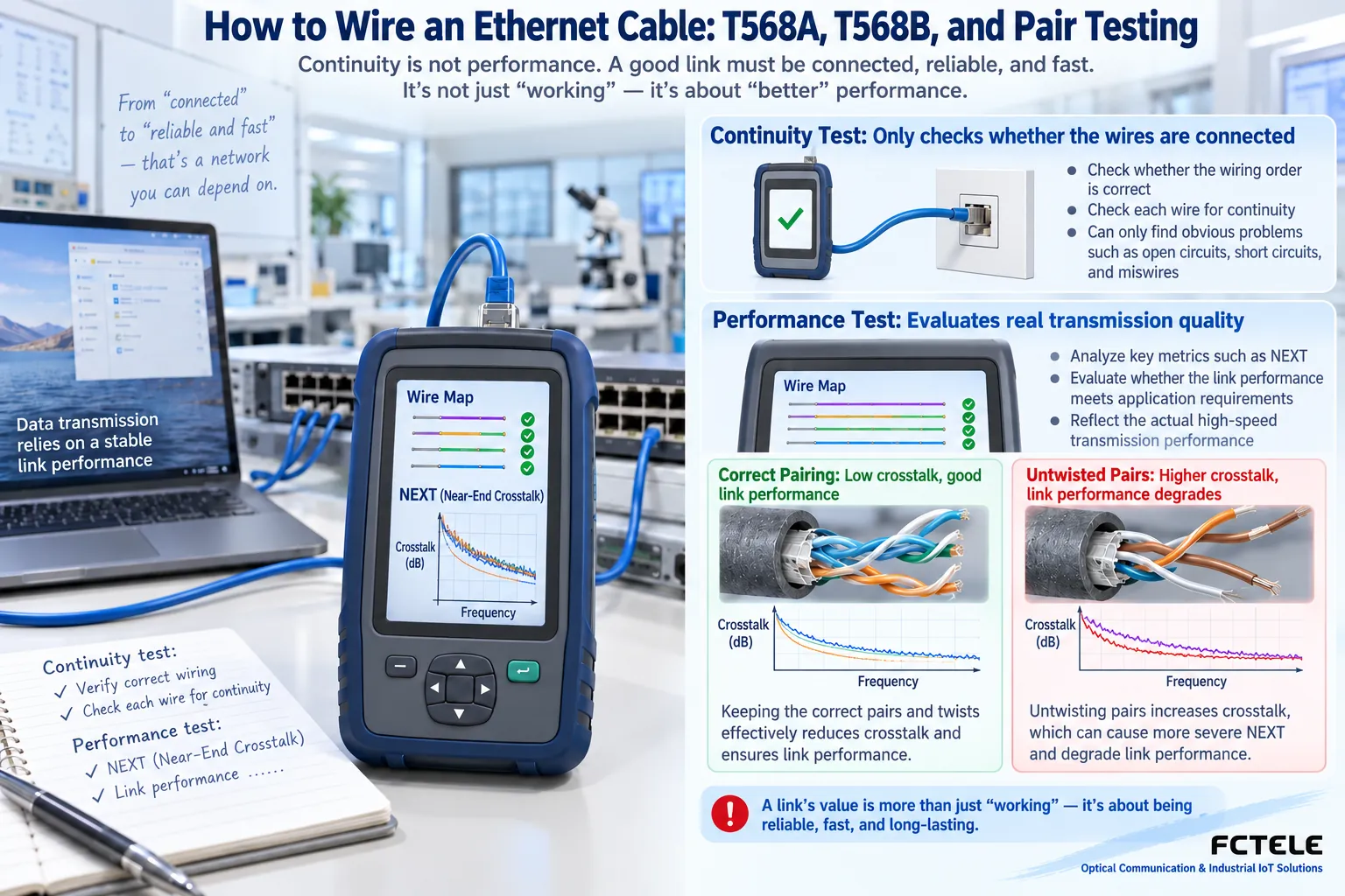
Possible causes include unstable contact in one pair, split pairs, device port capability, manual speed settings, or insufficient link performance. First check the actual negotiated speed at both ends, then use a known-good short patch cord for a back-to-back test to distinguish port problems from cabling problems. Low-cost wire-order testers may not be able to identify split pairs or quantify high-frequency performance.
Projects that need category certification should use compliant test equipment and test limits, and check corresponding indicators such as insertion loss, return loss, and near-end crosstalk. The test report should state whether it is a permanent link or channel test type; a single continuity photo cannot be treated as the entire acceptance record.
PoE cables must also carry the power supply load
Contact resistance, conductor quality, and DC resistance unbalance can all affect power supply stability and heat generation. If a camera works normally during the day but drops offline at night after the fill light turns on, in addition to the PoE power budget, also check the cable and termination. Do not assume that because the data connection is normal, the power supply load condition must also be acceptable.
After completion, label both ends, record ports and test results, and actually verify the target speed and service. If crossing buildings or covering longer distances is required, redesign the transmission medium rather than endlessly daisy-chaining network cables. Common length constraints for ordinary copper Ethernet channels should also be checked against the corresponding standards and site conditions.
References:Fluke Networks: T568A and T568B wire order.
Translated from the Chinese technical article. Source first published: 2019-11-13. Source last revised: 2026-10-13T23:18:15+08:00. Read the Chinese source
