


“Fiber optic converter” is a broad name. This article limits it to fiber optic transceivers in Ethernet scenarios: connecting copper cable Ethernet and compatible fiber optic Ethernet. It can solve the problem of media connection, but it cannot automatically interchange any interface or any protocol. Understanding the internal sending and receiving process is necessary to correctly judge its relationship with switches, optical modules, and optical modems.
First, distinguish whether it converts media or protocols
The same business data can pass through different transmission media, but the receiving device must follow the corresponding line and encoding rules. An Ethernet fiber optic converter mainly performs media adaptation between compatible Ethernet interfaces. The copper side and fiber side have different forms, but the business still belongs to Ethernet. Protocol conversion may change data organization, addresses, or application meaning, and requires special design. The two are like the difference between changing vehicles and translating languages, but the metaphor cannot explain actual encoding details. The device being called a “converter” does not prove it will translate all protocols. Procurement descriptions should state the Ethernet rate, optical port standard, and connection target, avoiding the use of only a vague product name.
How the sending side turns electrical signals into light
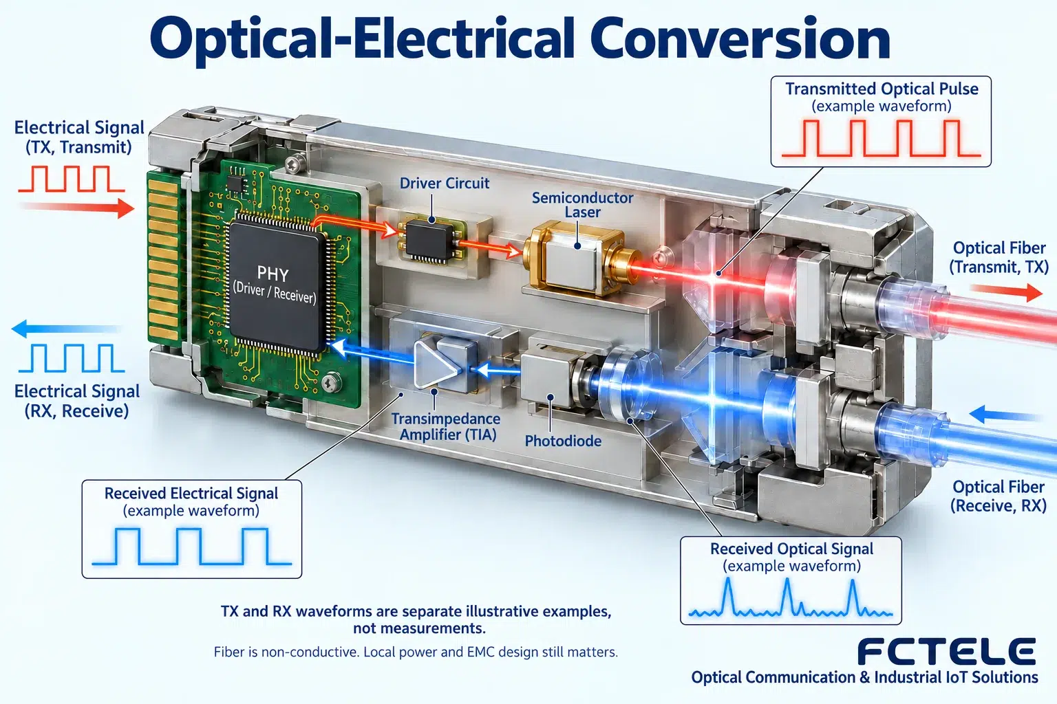
The copper port physical layer circuit receives the line signal, recovers the corresponding data and completes internal processing, then the driver circuit controls the optical transmitter. The information of light can be expressed through changes in intensity or other specified characteristics; the specific encoding depends on the interface scheme. A laser or corresponding light source provides the carrier, and the driver circuit applies the data to the sending process. The light source and the data source cannot be confused. The pulses in the figure only indicate that changes carry information; not all Ethernet standards use the same waveform. Some devices have buffers and switching structures, and conversion also has processing and propagation time, so it should not be called absolutely zero delay. Understanding this chain also helps to separate the phenomenon where the copper port is normal but the optical side fails.
Why can’t the receiving side recover data just by seeing light?
The detector converts the arriving light into current, the receiving circuit amplifies and processes it, and then judges the signal state under the specified timing. If the light is too weak, too strong, or the waveform is damaged, seeing light or detecting a link may still fail to stably recover every symbol. The receiving range, rate, and encoding must be compatible with the sending end. Readers can think of the receiver as a person who understands a language: hearing sound does not mean hearing the content clearly; but this metaphor cannot give a power threshold. Actual thresholds must be checked in the module manual, and signal quality must also be judged through error counts and service tests. A single green indicator light cannot rule out connector contamination, line attenuation, or receiver overload.
How it extends existing Ethernet connections
Under matching conditions, a converter can connect a certain copper cable connection to fiber, so that Ethernet devices at both ends continue to exchange data. The opposite end can be another compatible converter, or it can be a switch that supports the corresponding optical interface. The effective application speed is limited by the weakest link in the entire path; a fast optical port will not automatically upgrade a slow terminal. Distance is also related to the module and fiber cable conditions; not all single-mode products guarantee the same number of kilometers. Planning should check the fiber core, connectors, splices, and loss margin, satisfying both receive sensitivity and avoiding overload. The value of the device lies in connecting with existing interfaces; media extension cannot be equated with all improvements in network capacity, addresses, and service quality.
Benefits and boundaries in electromagnetic environments
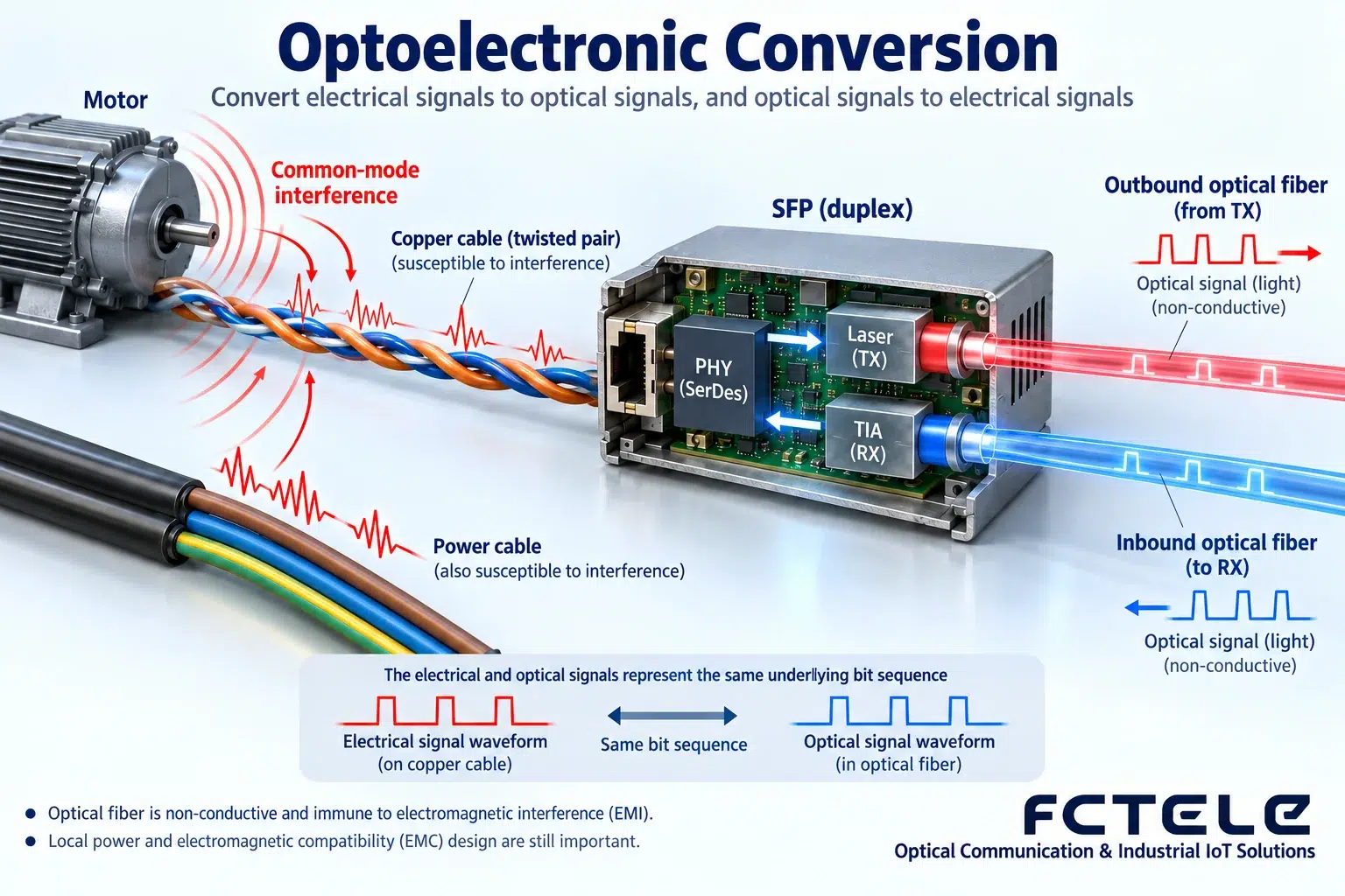
Copper conductors couple with the surrounding electromagnetic environment; motors, switches, and wiring methods may affect signals. The glass fiber core propagates through light and is not a data conductor that conducts electricity across buildings, so it has advantages in some environments. However, the converter still needs a local power supply, and the metal casing, grounding, and other copper connections also have electrical paths. An optical link cannot automatically eliminate local surges, bad power supplies, or improper grounding, and not all devices have the same isolation and protection capabilities. The figure draws the optical segment and local power supply separately, which is a reminder not to treat media characteristics as a safety guarantee for the entire system. Installation still needs to follow the corresponding product and on-site electrical regulations.
Differences from optical modules, switches, and optical modems
An optical module is usually a pluggable optical transceiver component for a host, requiring the host to provide power and interface processing; a standalone converter puts the related functions into a device that can be used independently. A switch usually connects multiple ports and forwards according to rules; some converters also contain a switching structure, but this cannot be used to infer that they have complete network management functions. A PON optical modem is a terminal that accesses the corresponding optical network protocol; an ordinary Ethernet converter cannot replace registration. Old leased-line optical modems also need to be distinguished by specific interfaces. Full-duplex Ethernet does not rely on the collision handling of traditional shared media to coordinate sending and receiving; historical half-duplex descriptions cannot be unconditionally applied to all today’s gigabit links. Product classification must follow actual interfaces and functions, not similar names.
Selection example: connecting an old copper-port terminal to an optical link
Suppose an existing terminal only has a copper port, and there is already fiber from the site to the equipment room. First confirm the terminal rate, service peak, and upstream optical port, then choose a matching standalone converter or other suitable solution. If the upstream is not compatible, a corresponding end device is needed, rather than blindly connecting cables. A single-fiber solution requires complementary wavelengths; a dual-fiber solution requires transmit to connect to the opposite end’s receive. The installation location also needs to check power, temperature, and maintenance space. If the service requires VLAN, multicast, or a specific frame length, these conditions should be written into the acceptance requirements; do not assume that “supports Ethernet” covers all behavior. This is an example of thinking and does not correspond to the performance commitment of any specific model.
How to do valuable testing after putting it into use
First establish a baseline in a permitted environment, then connect the formal optical path, and record the status and diagnostics at both ends. Test bidirectional real services, different frame lengths, and expected loads, and check whether error counts and alarms continue to grow. If an abnormality occurs, narrow the scope layer by layer according to power supply, copper port, optical port, forwarding, and application, changing only one variable at a time. Save the model, optical path number, and power data; use specified tools when cleaning connectors, and do not look directly at the light source. The general mechanisms described in the article do not replace the corresponding manual. The key to mastering an Ethernet fiber optic converter is not to believe in a “universal extender,” but to be clear about which segment of media it can change, which layer of problems it cannot solve for you, and to use evidence to confirm that the target service is truly stable.
Principle verification materials:Official material 1;Official material 2. The general mechanisms and examples in the article do not replace the corresponding model manual.
Translated from the Chinese technical article. Source first published: 2019-08-02. Source last revised: 2026-10-13T22:50:44+08:00. Read the Chinese source
