


Compare Ethernet networks with Fibre Channel storage networks, explain HBA, zoning, and storage mapping, and avoid mixing devices based only on optical port shape.
Both are called fiber switches, but their business may be completely different
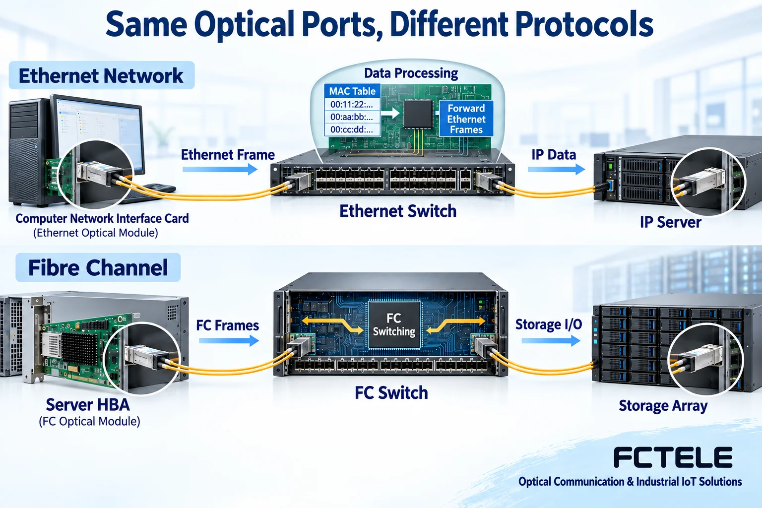
When judging a switch, the first step is to confirm whether it carries Ethernet frames or Fibre Channel storage communication. Ethernet switches often connect computers, industrial terminals, cameras, and IP servers; FC switches are usually in dedicated storage networks, connecting servers’ FC adapters and storage arrays. Both types of devices may use SFP-type modules and optical fibers, so you cannot judge the purpose only by the optical port shape, chassis size, or product name.
SAN stands for storage area network. It describes a network purpose dedicated to providing storage connections, but it does not mean every SAN must use FC. Ethernet can also carry some storage protocols. NAS usually provides access to clients through file services; it is not an “early stage” in switch development. Before buying, clarify whether you are accessing network file services, IP storage protocols, or FC storage targets, then check the server interface and device protocol.
Ethernet paths mainly check addresses and VLANs
In an Ethernet path, the terminal network card generates frames. The switch selects the output port based on MAC addresses and VLAN ranges, and when necessary, routing devices connect different IP subnets. Modules handle optical-electrical transmission and reception on the medium, but they do not turn an ordinary network card into an FC adapter. Common configuration items include port mode, VLAN, management address, link aggregation, and loop prevention mechanisms; whether each function exists depends on the specific product.
The optical ports of an Ethernet switch can become terminal connection or uplink interfaces, but this does not automatically change the network’s protocol. When Feichang Technology managed industrial switch product information lists functions such as VLAN, port statistics, mirroring, and spanning tree, you can use it to check Ethernet access and aggregation solutions. Its information cannot be used to prove that the device also supports FC zoning or storage array mapping; cross-protocol functions must have independent model evidence.
FC paths require servers and storage to work together
In an FC network, servers usually connect through an HBA. HBA stands for host bus adapter; here it specifically means a server adapter that supports the FC protocol. It hands host-side storage access to the FC link, reaching the target storage port in the switched network. The fact that an optical signal can enter a module only shows that the optical layer may be compatible; whether the port can log in according to the FC protocol, discover targets, and complete access also requires the relevant adapter, switch, and array configuration to be correct.
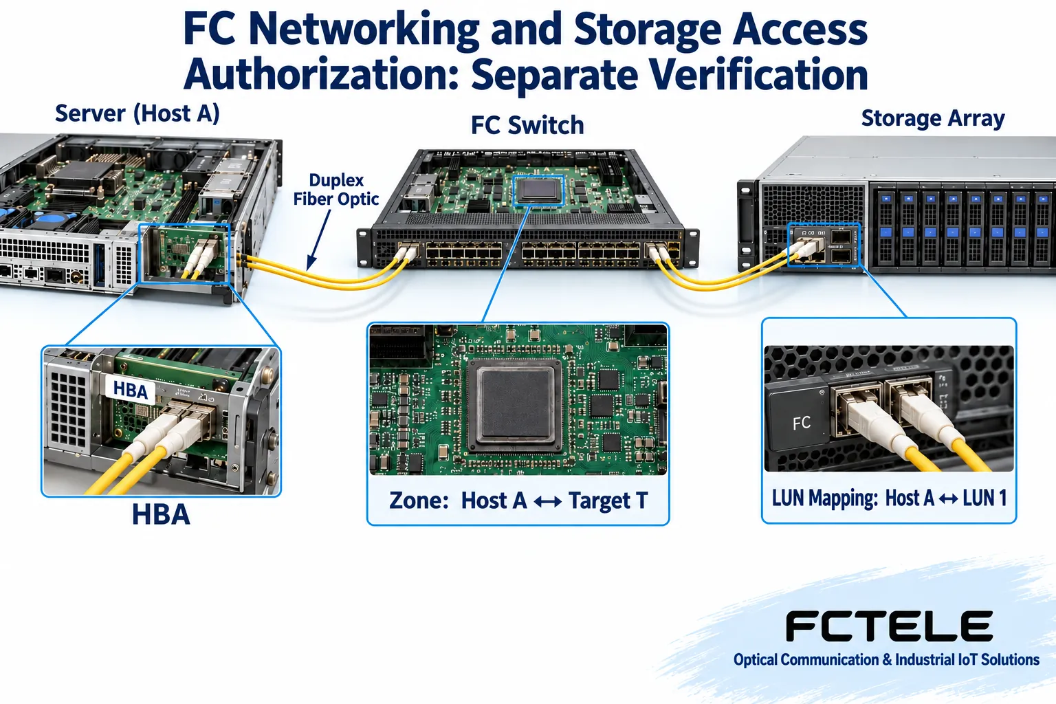
FC devices often use identifiers such as WWPN to identify ports. WWPN stands for World Wide Port Name, which is not the same configuration object as an Ethernet MAC address. Zoning is usually used to limit which initiators and targets can see each other; the storage array also needs host identification and logical unit mapping. LUN stands for logical unit number and is an object in storage access. Zoning allowing visibility does not mean the server has obtained access rights to a certain volume.
Verify visibility, authorization, and business success separately
For example, a server connects to an array through an FC switch. First check the HBA and switch port supported speeds and modules, then verify port login and identifiers. Next confirm zoning members, active configuration, and array host objects, and finally confirm volume mapping and that the operating system can recognize it. Only when every layer matches does the server have the conditions to use the corresponding storage. Seeing the optical port light turn on and immediately formatting an unknown disk neither proves the wiring is correct nor may destroy existing data.
Acceptance should first confirm authorized targets and data protection measures, then test according to the server, switch, and storage manuals. Multipath deployment also involves operating system software and storage support; dual fibers alone do not equal complete multipath redundancy. During maintenance, record identifiers at both ends, zoning, host mapping, and active configuration to ensure that after replacing a port or adapter, the corresponding relationships can be rechecked.
Optical compatibility and protocol compatibility are two separate checklists
Both types of networks should check module package, host support, fiber type, wavelength, connector, and optical budget. But even if these conditions appear consistent, the protocol and port mode may still differ. A module suitable for an Ethernet host may not work properly on a certain FC device; the same physical speed number cannot replace the manufacturer’s clear statement on protocol and compatibility.
FCoE is a technology that encapsulates FC frames into Ethernet. It requires corresponding converged network adapters, forwarding functions, and network conditions. It does not mean that any Ethernet switch with an optical module inserted can become an FC switch. If a project really uses a converged network, check device support and configuration requirements according to the complete solution; when there is no product evidence, keeping Ethernet and FC as two separately planned paths is the easiest way to avoid mistakes.
Check identity changes when replacing devices
Replacing an HBA or storage port may change the port name used for identification. Even if the original fiber is plugged back in, the old zoning and host mapping may not still apply. Record the old identifier, new identifier, and target volume, then update the configuration according to the authorized scope. Replacing Ethernet devices also requires checking port VLANs and management addresses, but this is not the same identification mechanism. In mixed networks, maintaining two separate lists makes errors easier to find than putting all optical ports into one port table.
How to write requirements clearly before choosing products
The requirements document should state the server’s existing interfaces, business protocol, target devices, speed, quantity, redundancy, and management method. If the task is to aggregate industrial cameras to a recording server, usually start from an Ethernet access and uplink solution; if the task is to connect existing FC HBAs and FC arrays, start from a storage network compatibility checklist. You cannot use “need a fiber switch” as the entire purchasing basis, nor can you infer from a single general description that all products have the same capabilities.
Troubleshooting should also be separated by protocol. If Ethernet services fail, check VLAN, IP, and routing; if FC targets are not visible, check port login, zoning, and array mapping. Randomly changing parameters across layers increases the scope of the fault. Keep the original configuration and logs, verify by changing one variable at a time, so you can determine whether the problem is in the optical layer, network control, or target access permissions, and form a reproducible handling record.
Information and illustration notes
The main text is written based on device working mechanisms and the following materials; specific specifications are subject to the ordered model and the latest manual. The illustrations are general mechanism diagrams.
Cisco SFP installation and safety instructions;Cisco FC and FCoE mechanism description;Feichang B-series Ethernet fiber transceiver information;Feichang managed industrial Ethernet switch function information
Translated from the Chinese technical article. Source first published: 2020-06-12. Source last revised: 2026-10-13T18:44:52+08:00. Read the Chinese source
