


Fiber media converters do not necessarily have to be placed as a pair of two units, but an optical link definitely needs a compatible opposite end. The other end can be a media converter of the same type, or a switch equipped with a matching optical module. Ordinary Ethernet media converters usually can both transmit and receive; the A/B end distinction of single-fiber BiDi is mainly complementary wavelengths, not “one unit only transmits, one unit only receives.”
Why do common installation diagrams show two units?
Assume both end devices only have RJ45 electrical ports, and the distance in between is relatively far, requiring fiber transmission. The left-end media converter converts the electrical signal into the corresponding optical signal, and the right end converts the received optical signal back into Ethernet electrical port data, thus forming “terminal—media converter—fiber—media converter—terminal.” Two devices are a way to solve fiber extension between two electrical ports, not the only form of all optical connections.
If the switch on the right already has a suitable optical port or SFP slot, it may be possible to use a “media converter—fiber—switch optical port” connection. In this case only one external media converter is needed, but the optical module inside the switch still performs the optical transmit and receive function at the other end. Not having a second external box does not mean there is no receive and transmit circuit at the far end of the fiber.
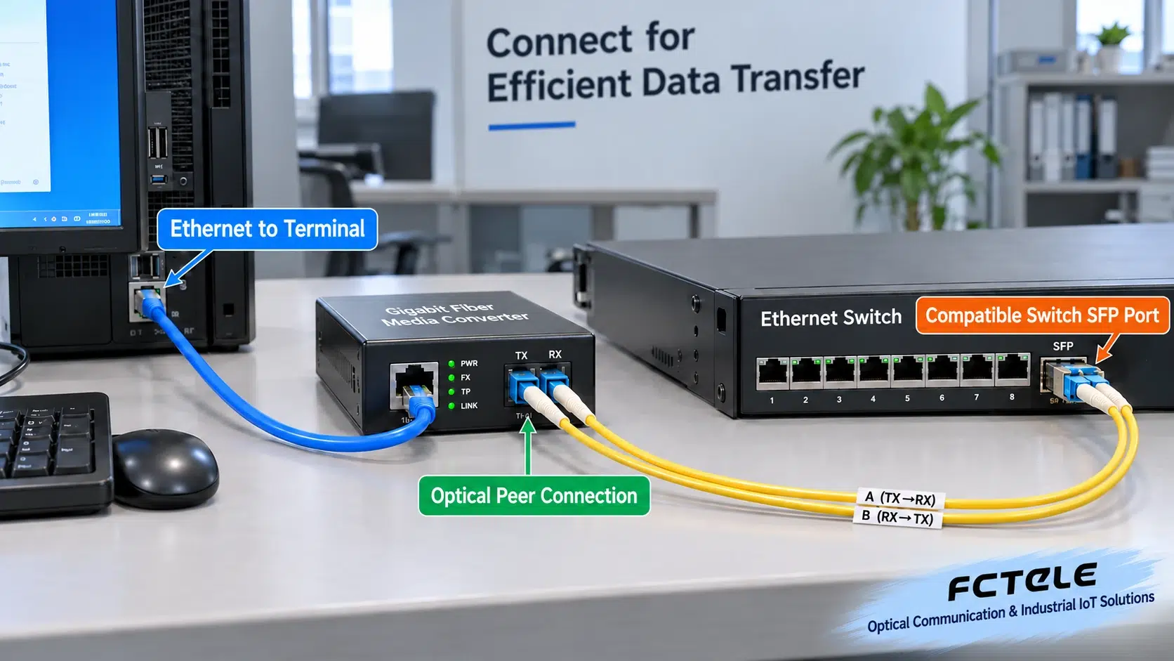
Each unit can transmit and receive; TX and RX each handle one direction
TX is transmit, RX is receive. A dual-fiber link usually assigns the two directions to two fiber strands: A-end TX connects to B-end RX, and B-end TX connects to A-end RX. A common dual-fiber SFP has two side-by-side optical interfaces, TX and RX, and cannot be drawn as “each direction needs one SFP,” nor can the entire A end be treated as the transmitting end and the entire B end as the receiving end.
Ethernet services can communicate bidirectionally, and the transmit and receive circuits of an optical module each handle one direction. The opposite optical port must recognize the same signal specifications; otherwise, even if the interface can be plugged in or there is even light, it does not mean an effective data link can be established. Successful negotiation on the network cable side also cannot prove that the fiber side matches.
Why is single-fiber BiDi often said to “require A/B pairing”?
BiDi uses different wavelengths to place the two directions on the same fiber strand for transmission. For example, the A end transmits 1310nm and receives 1550nm, and the B end transmits 1550nm and receives 1310nm. Both sides can transmit and receive; they simply have different wavelengths for transmit and receive. The internal wavelength-division device separates the different wavelengths, so it is not necessary to lay one fiber strand for each direction.
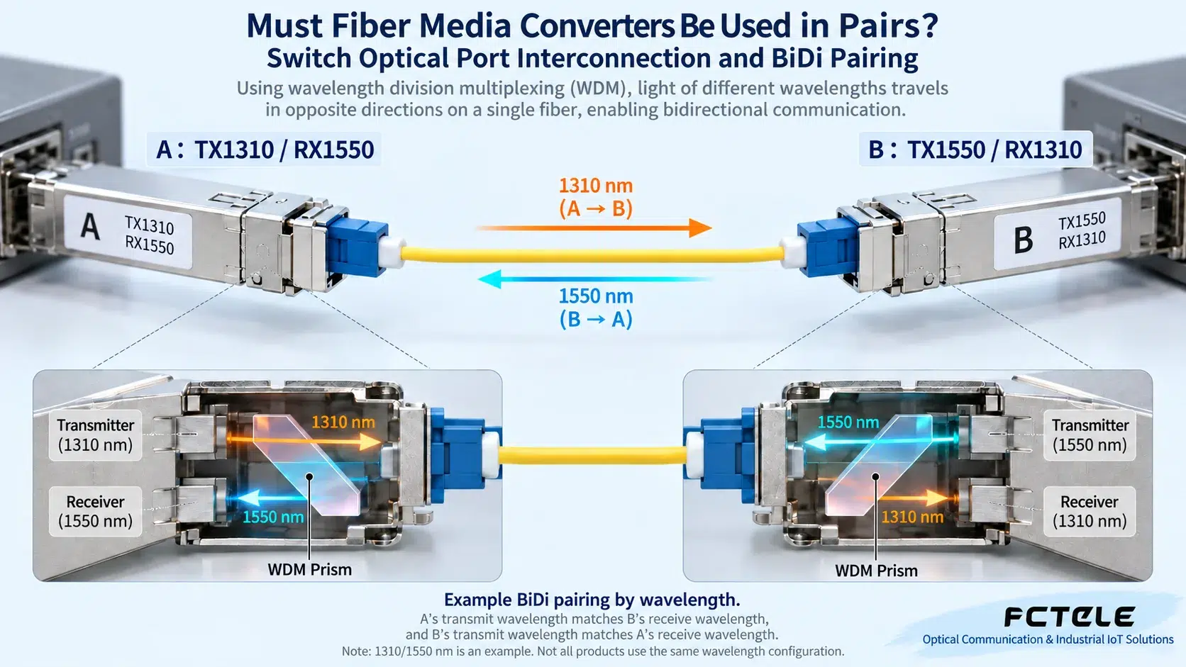
Manufacturers may use A/B, U/D, or other naming; you cannot assume that the same letters marked by different manufacturers represent the same wavelengths. There are also modules using 1310/1490nm or other combinations, so you should directly check the TX and RX wavelengths, rate, distance, and optical power range on the label and specification table. Two single-fiber modules with the same wavelength configuration usually cannot become a complementary pair simply by changing the installation location.
The real matching checklist is more important than “same brand”
First check the rate and optical port protocol. 100M and 1000M, fixed rate and multi-rate support ranges cannot be mixed by guesswork; the fact that some electrical ports support multiple rates does not mean the optical port also automatically supports all rates. Second check the fiber type: single-mode modules should be paired with suitable single-mode fiber, and multimode modules with suitable multimode fiber, and confirm the connector, endface type, and cable quality.
Third check wavelength and direction: dual-fiber requires TX/RX crossover, and BiDi requires complementary wavelengths. Fourth check the optical power budget: the power received at the far end must be both higher than the receive sensitivity and not exceed the receive overload upper limit. A long-distance module connected to a very short link is not necessarily safer; a short-distance module also cannot extend transmission distance indefinitely just because the fiber core is intact.
Finally confirm the device’s support for the SFP model. The same slot form factor cannot replace a compatibility statement, and management and monitoring functions may also differ. Cross-manufacturer devices have a chance of interoperating normally, but end-to-end verification should be performed using the planned modules; you cannot promise interoperability based only on similar product names.
Troubleshoot by symptoms; do not keep blindly swapping A/B ends
There is another easily confused situation: fiber media conversion equipment with multiple electrical ports may include switching functions, while some products emphasize independent channel transmission. You cannot assume that the forwarding relationship between ports is the same just from the name “photoelectric conversion.” When transparent extension, VLAN pass-through, or multi-service isolation is required, you should check how the device handles Ethernet frames, and if necessary test with tagged services and multiple terminals.
At delivery, it is recommended to keep a link comparison table listing the devices and module models at both ends, TX/RX wavelengths, fiber core numbers, connector types, test power, and service results. Post this information near the ports and patch panels so that later replacements do not require guessing A/B based on box color or site location. Spare parts should also be prepared as complementary combinations, to avoid having only modules of the same wavelength direction left during a fault.
When the optical link does not light up, first confirm that both ends are powered, the modules are seated, the protective caps have been removed, and the endfaces are clean; check the dual-fiber crossover or BiDi wavelengths, then check the rate and module data. Verifying with a known-good short patch cord can separate device mismatch from on-site long-link problems. Do not look directly into optical ports or judge by eye whether light is emitted; use suitable instruments and safe operating methods.
If the optical light is on but the service does not work, further check the electrical port connection, terminal IP configuration, VLAN, or device management settings. Establishment of the optical link only indicates that the physical or link conditions have reached the corresponding state; it does not automatically guarantee that the application service is correct. During troubleshooting, change only one condition at a time, and keep the models at both ends, optical module labels, and power test results.
Reference:Cisco Gigabit SFP information Demonstrates the complementary wavelength mechanism of single-fiber BiDi. The examples in this article do not replace specific module specifications; “used in pairs” should be understood as compatible optical transmit and receive capabilities working together, not as necessarily having to buy two boxes with the same appearance.
Translated from the Chinese technical article. Source first published: 2019-12-05. Source last revised: 2026-10-13T23:45:12+08:00. Read the Chinese source
