


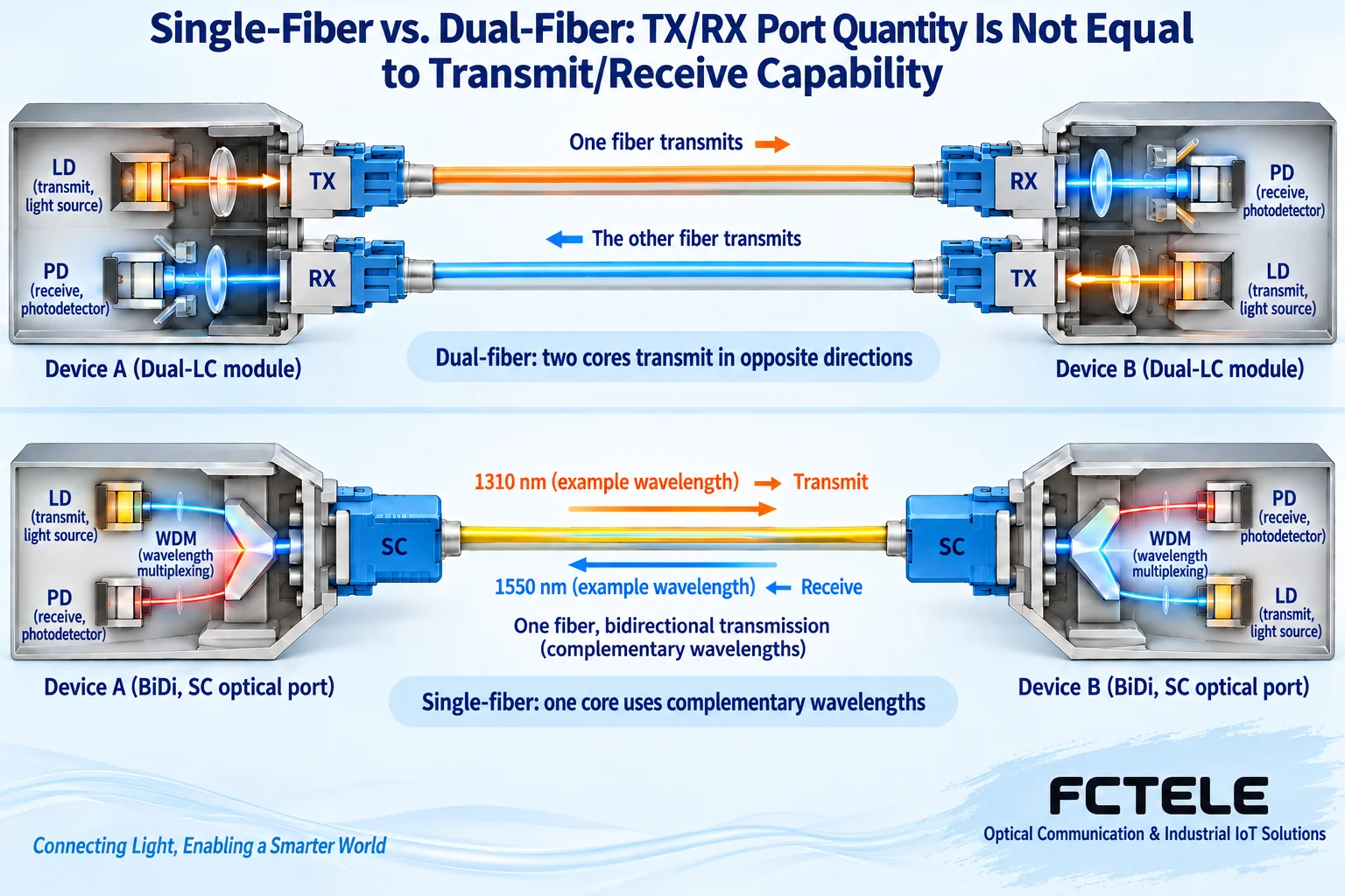
TX means transmit and RX means receive. Typical duplex converters connect local TX to remote RX, with the other fiber carrying the reverse direction. Single-fiber BiDi uses complementary wavelengths for both directions on one fiber. Normal Ethernet converters transmit and receive; they are not a transmit-only box paired with a receive-only box.
Read port roles rather than enclosure position
Ethernet needs requests and replies and may carry simultaneous traffic in both directions. The transmitter converts electricity to light, and the receiver recovers incoming light. TX and RX name those roles. A transmitter remains TX whether it is local or remote.
Duplex optical ports serve different directions. Port color, enclosure orientation and jumper color cannot replace labels. Even a duplex connector holding two cores needs polarity verification; a paired plug does not automatically prove correct crossing.
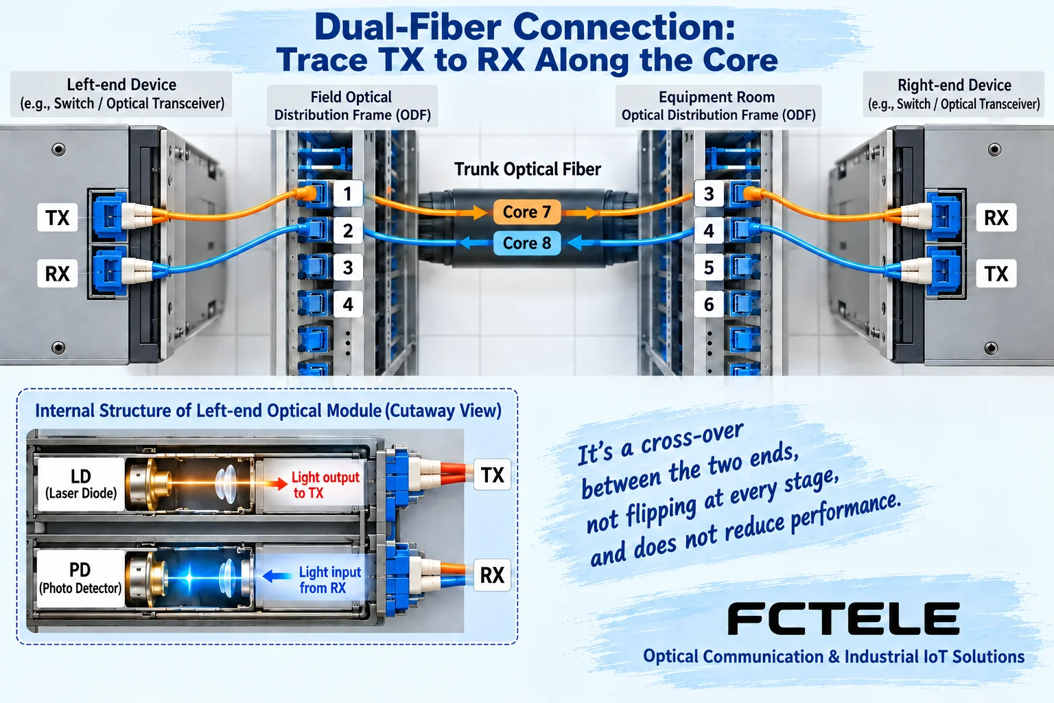
Why duplex crossing is necessary
TX-to-TX sends light from both ends into one core without the required receiver path; RX-to-RX has no transmitting source. Correct crossing combines two one-way paths into a two-way link. Trace complete core identifiers through patch panels rather than only the jumper beside the device.
Direction alone is insufficient. Mismatched rates, fiber modes, wavelengths or power windows may still prevent operation. SC and LC describe connector types. An adapter changes physical connections, not transmission protocols.
How one fiber carries both directions
Common BiDi uses different transmit/receive wavelengths with optical combining/separating components. For example, one end sends 1310 nm and receives 1550 nm, and the other does the reverse. This common teaching example does not define every product.
A/B labels require actual TX/RX parameters. Two A units may not complement each other, and manufacturer letter definitions cannot be applied blindly across brands. Also check protocol, speed, permitted loss and receive overload.
Verify the optical path safely
Check labels and wiring records, then test with known-compatible equipment and clean short jumpers in permitted isolation. Measure receiver-side power on the field line and compare the actual module documentation. Light on a line does not prove valid decoding.
Never look into optical ports. End-face inspection equipment must be used under procedures confirming source safety. Inspect, clean when needed and reinspect rather than repeatedly mating dirty connectors. Record direction and power without mixing endpoint results.
Why traffic may fail with correct TX/RX
A normal optical link establishes only part of the physical conditions. Copper negotiation, VLANs, IP addresses, gateways and access policies may still fail. Check optical status, copper link and the particular service in order. Continually swapping fibers cannot repair upper-layer settings.
For one-direction errors, compare both power readings, error counters and receive ranges, then inspect the corresponding transmitter, core and connectors. Change one variable at a time and preserve results to distinguish equipment, line and configuration causes.
Avoid wiring mistakes in procurement and handover
List speed, fiber type/count, TX/RX wavelengths and peer equipment. Check FCTEL models in the product center. Label jumpers and patch-panel cores at handover, identify complementary single-fiber parameters and retain measured power and service results.
A converter may connect to a compatible switch optical module, so matching-looking boxes are not mandatory. Removing one separate enclosure does not remove the need for compatible optical transmission and reception at that endpoint.
Trace complete fibers through patch panels
Start records at the device port rather than jumper color. If field TX enters panel port 1 and that port corresponds to trunk core 7, trace core 7 to its room-side panel port and confirm its jumper reaches room RX. Write a separate complete return route from room TX. The routes cannot share one core at an intermediate point, and panel port order does not define device TX/RX direction.
A duplex clip joins connectors mechanically, but premade jumpers and panel arrangements can have different end-to-end polarity. Crossing means the final transmitter reaches the receiver, not that every intermediate segment must be reversed again. An extra reversal can break an already correct path. Follow component procedures for clips or connector swaps, use a maintenance window and update labels and the complete route.
Record at least local TX, field panel port, trunk core, room panel port and remote RX, separately for the reverse direction. If old labels are unreliable, confirm continuity with appropriate tools under safe isolated conditions. Continuity does not prove acceptable loss: measure power and verify service too. Never inspect for light with your eyes or look into a live optical end face.
Match device connectors to the ordered configuration. The FCTEL B-series single-optical/single-copper Gigabit page lists several fibers and interfaces. Delivered versions may use fixed optics or pluggable modules; a series photo cannot specify every unit. Check labels and orders before choosing jumpers and panel accessories. Copper automatic crossover concerns Ethernet cable wiring, not duplex optical end-to-end polarity. Confusing these functions can hide incorrect fiber wiring. Keep the port register consistent with final connections and save directional test results.
Translated from the Chinese technical article. Source first published: 2020-05-12. Source last revised: 2026-10-13T15:39:27+08:00. Read the Chinese source
