


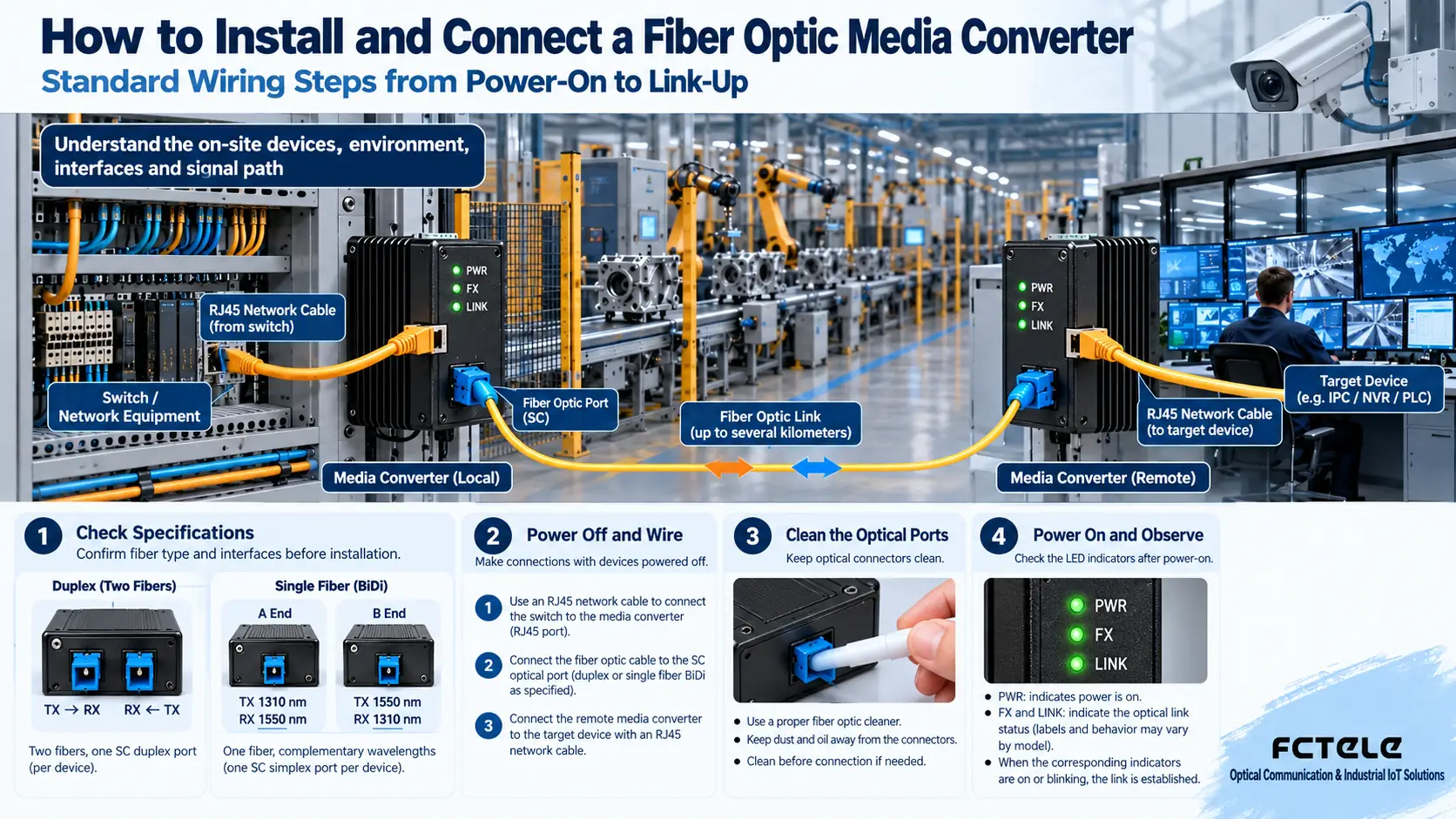
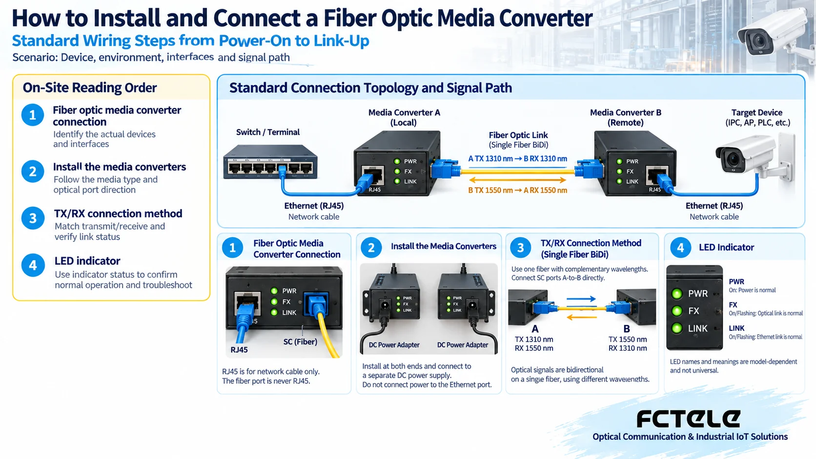
Let’s start with the conclusion:This article only solves the problem of “how to get connected step by step on site.” The standard link is: a terminal or switch enters the local media converter through an RJ45 network cable, then goes through fiber to the remote media converter, and finally connects to the target device with a network cable. The recommended fixed installation order is: check specifications, power off and wire, clean the optical ports, power on and observe, then test section by section — this makes it easy to quickly locate faults.
How to read the diagrams: This article is organized around “How to Install and Connect a Fiber Optic Media Converter: Standard Wiring Steps from Power-On to Link-Up,” using two approaches: first, clearly marking the connection roles of the fiber optic media converter on the diagram, and second, matching the fiber optic media converter installation with each port one by one. When reading, first confirm the fiber optic media converter connection along the signal or status direction, then use the fiber optic media converter installation to check the boundaries, and finally trace any abnormal phenomenon back to the specific interface, medium, or protocol layer.
1. How to Install and Connect a Fiber Optic Media Converter: First Clearly Mark the Connection Roles of the Fiber Optic Media Converter on the Diagram
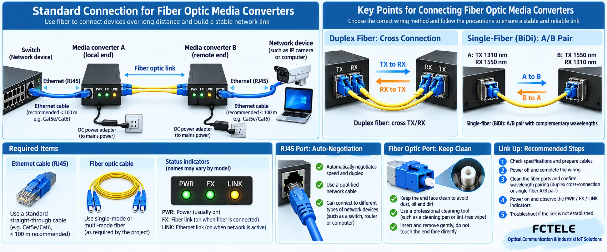
Dual-fiber ports must have the local TX connected to the remote RX, and the local RX connected to the remote TX; single-fiber BiDi requires that the A/B ends have complementary wavelengths. Establishing an optical port link only shows that the optical layer is basically usable; it cannot prove that VLAN, IP, speed/duplex, or service configuration is correct. Excessive optical power can also saturate the receiver at short distances, so you cannot focus only on insufficient attenuation.
The point of this kind of article is not to memorize one particular wiring method, but to fix the interface roles, wire order, power supply, grounding, and acceptance sequence. Use diagrams to explain the fiber optic media converter installation and connection steps: device power-on, RJ45 network cable, optical port TX/RX, single-fiber A/B ends, speed/duplex, and LED indicator acceptance. This article is organized around “fiber optic media converter connection, fiber optic media converter installation, TX RX wiring, media converter LED indicators.” During implementation, mark the role of each interface and path on the diagram, record the differences between normal and fault states, and confirm the solution boundaries with actual measurement results.
2. How to Install and Connect a Fiber Optic Media Converter: How the Fiber Optic Media Converter Installation Corresponds to the Ports One by One
First check single-mode/multimode, single-fiber/dual-fiber, wavelength, speed, and interface type; then fix the device, connect power, plug in the network cable and fiber. After power-on, observe PWR, FX/LINK, and TP/LINK in sequence, and finally accept it through continuous Ping, throughput, and power-off recovery tests. If the optical light does not turn on, you can swap the two cores of the dual-fiber cable to rule out reversed TX/RX, but do not blindly repeatedly plug and unplug uncleaned end faces.
Acceptance suggestion:Follow the sequence of “specification check — single-link test — fault simulation — recovery confirmation — record archiving,” changing only one variable at a time to avoid mixing configuration, medium, and device problems together.
3. How to Install and Connect a Fiber Optic Media Converter: Section-by-Section Acceptance After Wiring Is Complete
4. How to Install and Connect a Fiber Optic Media Converter: How to Judge Reverse Connection, Mismatch, and One-Way Link
Must both ends of a fiber optic media converter be the same brand?
Not necessarily, but the fiber type, wavelength, speed, interface, and encoding method must be compatible. Special protocols should preferably be used in pairs.
Should the fiber be connected first or should power be turned on first?
In engineering, usually complete and recheck the wiring first, then power on uniformly and observe the status, to reduce live plugging and misjudgment.
What should I do if the FX light is on but the network is not working?
Continue checking the electrical port link, speed/duplex, VLAN, IP address, loops, and upper-layer device policies.
The illustrations are general mechanism diagrams and do not represent specific model physical objects or measured data.
Translated from the Chinese technical article. Source first published: 2019-07-24. Source last revised: 2026-10-13T19:01:44+08:00. Read the Chinese source
