


Splicing connects glass optical fibers, not two outer jackets
Fiber optic splicing aligns and fuses the ends of two compatible optical fibers to form a long-term connection point. A common field task is to extend a line, or to connect a pigtail with a connector to an optical cable fiber core. What the equipment ultimately sees is the complete optical path; whether the splice point is made well affects received power and line reliability, but splicing will not turn single-mode into multimode, nor will it change the protocol used by the equipment.
The cable outer jacket provides mechanical and environmental protection. The glass optical fiber has a core, cladding, and an outer coating. Construction first handles the cable, then strips the specified coating length from the fibers to be spliced. You cannot strip off the entire cladding, nor can you simply glue the jackets together and consider the optical path connected. The end face and axis determine whether light can effectively enter the other fiber core.
First establish a splice table, then prepare tools and the site
The splice table should record the cable number, loose tube, fiber core number, destination, and spare use. Color helps identification, but it cannot replace confirmation of numbers by both sides; for cables from different manufacturers or with different core counts, each item should be matched according to the actual markings. First verify which fiber cores are carrying traffic, arrange a maintenance window, and prevent mistakenly cutting a live link.
The equipment manual determines the strip length, cleave length, fixtures, and splicing program. Do not treat the seconds and dimensions of an old model as universal steps. Prepare suitable stripping tools, cleaning materials, a cleaver, protection sleeves, a splice tray, and test instruments. Arc splicing should be completed in a suitable construction environment; collect glass debris in a centralized way, do not wipe it with bare hands, and do not test the machine in an environment with explosion risk.
Why cleaning and cleaving come before alignment
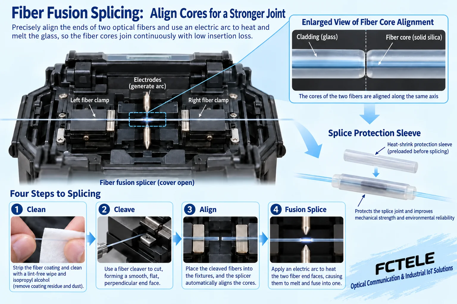
According to the manual, first thread on the protection sleeve, then strip the coating and clean the bare fiber. Oil contamination, coating residue, and dust may affect clamping, the end face, or fusion. After cleaning, use a precision cleaver to form a suitable end face; the cleave here relies on a controlled scratch and break, not on cutting a thin line with ordinary scissors. Once the end face has been cleaved, do not touch it casually again.
Place the two fibers into the corresponding fixtures, and the equipment checks the end faces and performs alignment. Core misalignment, an angled end face, or contamination may all prevent light from coupling sufficiently into the other end. Do not use visual inspection of “it is connected” to replace equipment checks; if the check fails, prepare again according to the manual rather than repeatedly forcing an arc discharge.
After arc fusion, splice protection is still needed
The fusion splicer uses a controlled arc to heat and fuse the end faces. Some equipment aligns by core image, while others use methods such as cladding alignment; the actual mechanism and applicable fibers are determined by the model. The splicing program needs to match the fiber type and site conditions. Automatic mode does not mean that any material can be spliced unconditionally.
After completion, check the equipment prompts, then move the sleeve to the splice position as required and perform heat-shrink protection. The sleeve’s task is to protect the splice that has already been formed; it cannot repair internal bubbles or misalignment. When placing it into the splice tray, keep the specified excess length and bend radius, and avoid crossing, squeezing, pulling, or pinching. Radius requirements are based on the cable and tray documentation, and construction is not completed by saying “the larger the better.”
Why the fusion splicer’s loss estimate is not acceptance
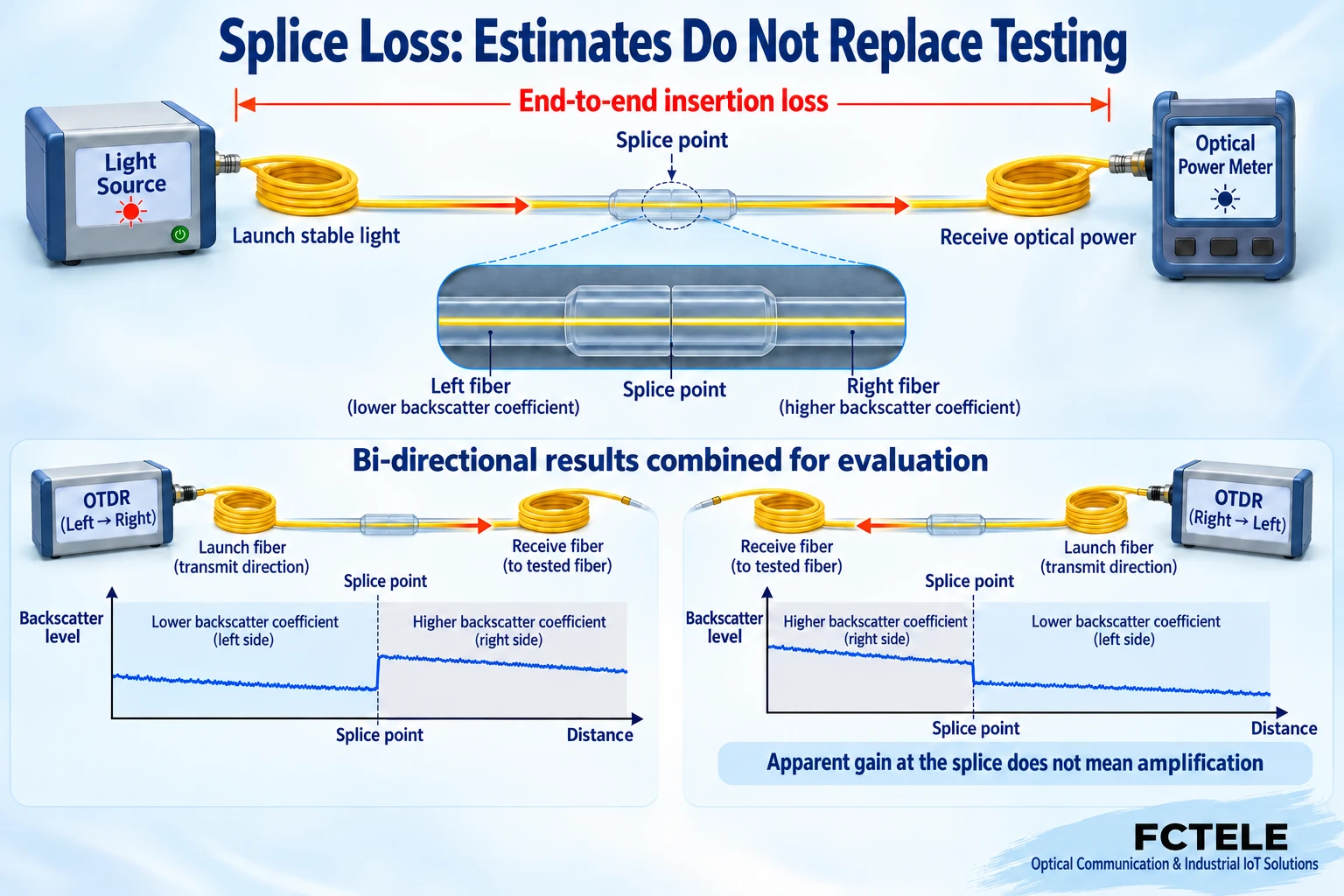
A fusion splicer usually estimates splice loss based on images and a model. It is suitable for helping judge whether to redo the splice, but it is not an actual insertion loss measurement of the entire optical path. The line also has effects such as fiber attenuation, connectors, patch panels, and bends. A splice with a very low estimate cannot prove that the final receiver will definitely have sufficient power.
A light source used with an optical power meter can test end-to-end insertion loss. Before testing, a reference must be set according to the corresponding method. OTDR, or optical time-domain reflectometer, locates line events through changes in backscattered light over time, and is suitable for observing splices and abnormal positions. The two types of tests answer different questions, and one OTDR screenshot cannot replace all link acceptance.
Why the same splice should be considered in two test directions
The backscatter characteristics of the fibers on the two sides differ, which can make the event loss observed by OTDR from one side appear higher or lower, or even appear as an upward step that looks like gain. This does not mean that a passive fusion splice has generated optical energy. Under applicable conditions, measure in both directions and combine the results, keeping the test wavelength, direction, range, and raw records.
Launch and receive fibers are used to help observe events near the two ends of the line; their length and settings should match the instrument and task. When adjacent events are too close, the instrument’s resolution and dead zone also limit judgment. Acceptance values are determined by project requirements and applicable test methods; do not impose a single loss number from the internet on all lines.
How to check the complete optical path when connecting to Feichang Technology equipment
The Feichang Technology B-series transceiver categories and 1-fiber-4-copper details can serve as an entry point for checking optical and electrical interfaces. Multi-copper-port aggregation equipment also has a shared uplink; a qualified splice loss does not mean the service capacity is automatically qualified. The copper port rate wording in the details differs, and the delivered specification should be confirmed; this article does not copy conflicting numbers.
For each line, record the equipment at both ends, module, wavelength, single-mode or multimode, fiber core, and port direction. Connector cleaning, received power range, and actual service still need to be verified. After the splice closure sealing and strain relief are completed, retest to avoid new bend loss from fiber routing or installation. Do not look directly into optical ports, and do not end acceptance just because a port light is on.
Deliver a record that can be reviewed later
Delivery materials should include the splice table, fiber core routing, splice locations, test methods and raw files, as well as changes before and after troubleshooting. If a service is down, first use the records to distinguish port configuration, equipment power, and optical path, then locate the specific event, avoiding blind re-splicing just because a splice is seen.
A good splicing process consists of identification, preparation, fusion, protection, and testing together. Protective materials cannot replace fusion quality, fusion splicer prompts cannot replace line measurement, and link measurement cannot replace service verification. Only by completing these tasks separately can future maintenance personnel know where this fiber is connected, how it was tested, and whether it can carry the current service.
Documentation note: The principle diagrams have been checked for technical content and are used to explain general mechanisms; they are not product photos or measured records. Specific interfaces, modes, and capabilities are subject to the selected model, version, and on-site verification.
Verification materials:FOA: Fiber optic splicing and protection
FOA: OTDR testing and measurement limitations
Feichang Technology B-series fiber optic transceivers
Feichang Technology 1-fiber-4-copper transceiver details
Translated from the Chinese technical article. Source first published: 2021-12-10. Source last revised: 2026-10-13T13:49:23+08:00. Read the Chinese source
