


When reading fiber optic terminal parameters, you should understand service interfaces, fiber media, wavelength, optical power, and transmission capacity separately. Single-mode/multimode describes the fiber propagation mode; single-fiber/dual-fiber describes the number of fiber cores used; dBm describes absolute optical power; dB describes loss or a ratio. The nominal distance in a model number is only one selection condition; you also need to check service compatibility at both ends and the actual optical link budget.
First look at “what is transmitted,” then look at “how far it is transmitted”
Fiber optic terminal is a broad product name; it may transmit video, telephone, serial port, or multiple services. Names such as SDI, HDMI, RS485, FXS/FXO indicate service interfaces or roles, not fiber types. The number of channels is also not equal to the number of Ethernet ports. How many channels the device can transmit and what format each channel uses need to be listed separately.
“Digital” does not mean all digital signals can be input; “transparent” usually means that within the supported range the service data or format is preserved, and it does not mean any rate and protocol are compatible. When you see SFP, you should know it describes a pluggable module form, not an unconditional promise of interoperability.
What single-mode, multimode, single-fiber, and dual-fiber each answer
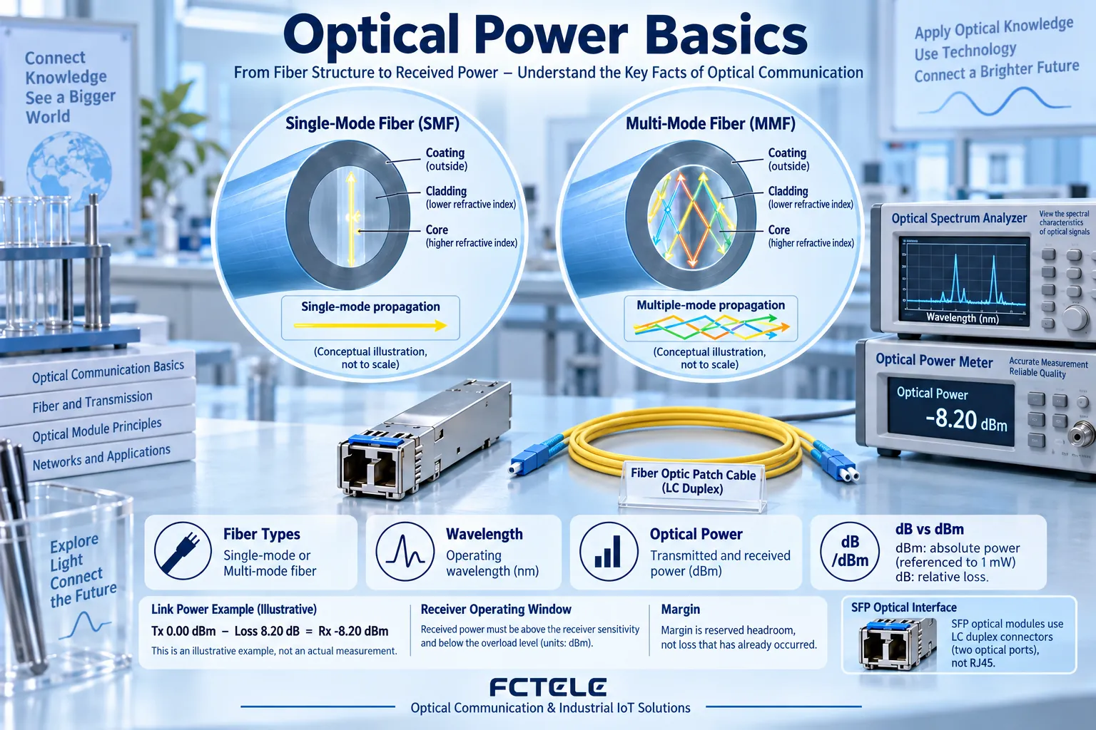
Single-mode and multimode focus on the modes a fiber can propagate. Common single-mode fiber cores are thinner, multimode fiber cores are thicker, and multipath propagation may bring modal dispersion; actual performance is determined jointly by fiber core grade, wavelength, rate, and transceiver, and cannot simply be written as “multimode must only be tens of meters.”
Single-fiber BiDi usually uses different wavelengths to separate the two directions, while dual-fiber usually uses one fiber for transmit and one for receive to form a bidirectional link. Therefore, single-mode is not equal to single-fiber, and multimode is not a synonym for dual-fiber. Connectors such as SC and LC indicate the mechanical interface; UPC and APC indicate the endface polishing method; compatibility cannot be judged only by the color of the pigtail.
dBm and dB: the pair of units most easily confused
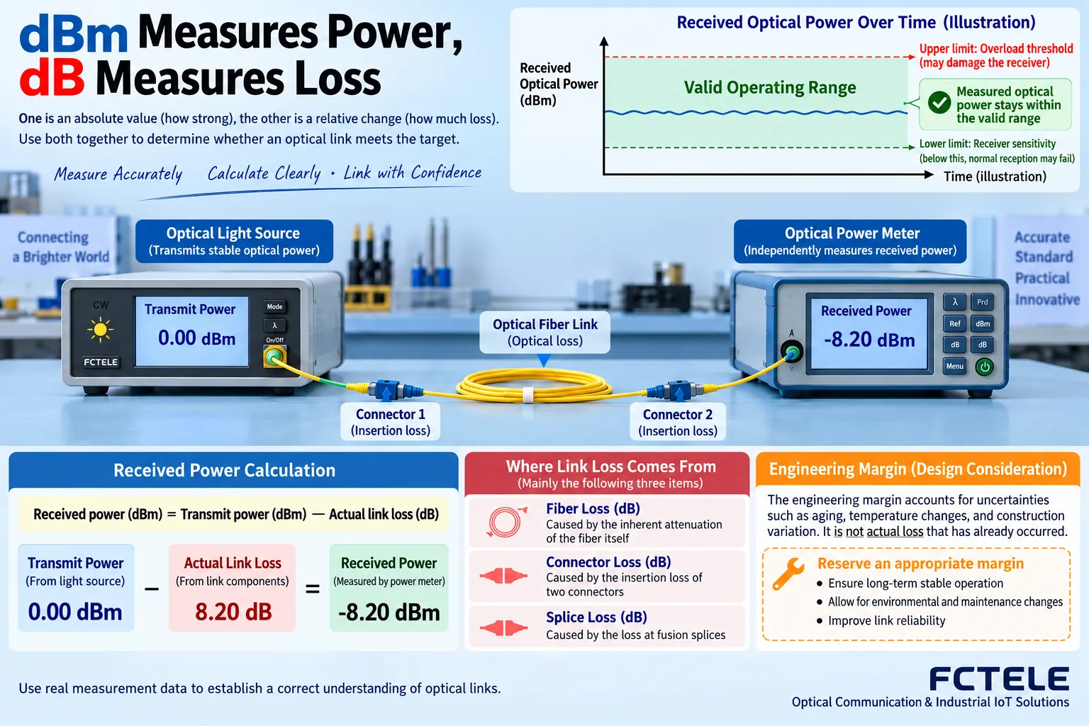
dBm uses 1 mW as reference to express absolute power; 0 dBm equals 1 mW, and a negative number does not mean there is no light. dB expresses the ratio of two quantities and can be used to describe optical path loss. Transmit power is a dBm value, and attenuation along the way is several dB; the two cannot be mixed up as the same kind of parameter.
A common estimate is:Received power ≈ transmit power − total link loss. Total loss includes fiber attenuation, connectors, splice points, and other device losses. The receiver has a lower sensitivity limit and also an overload upper limit; receiving too weak or too strong can both affect operation, and you cannot assume that the higher the power, the better.
How distance, bandwidth, and bit error rate are each used
Nominal distance reflects the manufacturer’s design range under agreed fiber and link conditions; additional field connectors or contaminated endfaces may consume margin. Bandwidth or rate describes transmission capability and does not automatically mean every service channel can exclusively use all capacity; multi-service multiplexing also depends on channel configuration and format limits.
Bit error rate reflects the proportion of erroneous bits in digital transmission, and measurement requires clear data volume, time, and conditions. “No errors seen” for a short time cannot prove that any long-term operation has no errors. Latency affects the time at which sound, image, or control messages arrive, and stability and jitter may also be more important than a single average value.
Turn a page of specifications into procurement questions
First write down the input services, interfaces, channels, and formats; then write the fiber type, length, connectors, and number of fiber cores; next check the rate and wavelength at both ends; finally verify power and environmental requirements. For dual-fiber, confirm TX to RX; for single-fiber, confirm complementary wavelengths. Temperature, protection, power supply, and management functions must be based on the specific model, not inferred from the product name.
Maintenance records should save power readings, error counts, and alarm baselines. When an abnormality occurs later, only then can you distinguish changes in optical path loss, changes in device configuration, and service faults, rather than judging that everything is normal just because “the light is still on.”
A budget example without fabricated device values
Take a certain model’s minimum transmit power and receive sensitivity; the difference between the two can help estimate the allowed loss range. Then deduct engineering margin and compare with expected fiber loss, splice loss, and connector loss. If the expected loss is already close to the budget, you should not judge it as acceptable just because the kilometer count is less than the nameplate distance; you should improve the optical path or choose an appropriate transceiver configuration.
When calculating the weak-light boundary, focus on minimum transmit power and receive sensitivity; when checking the strong-light boundary, also compare maximum transmit power with the overload upper limit. Both directions must be calculated, especially because the wavelengths and device conditions at the two ends of BiDi differ. Do not use a single measurement’s “better value” to replace the worst condition in the specifications.
An optical power meter gives power under specific measurement conditions, and an OTDR can help observe events along the line and locate loss changes, but the two have different uses. Measurement wavelength, test cord, and connection method affect the result; appropriate instruments should be used and conditions recorded. Webpage parameters cannot replace on-site testing.
When encountering a manufacturer’s proprietary abbreviation, first look for its definition in that model’s manual. For example, LINK, LOS, and alarm lights may represent different layers, and steady on and blinking are not standardized either. Technical terms have a standards background, but abbreviations on a product panel still differ in implementation; only by recording the definition source and test conditions together can you truly understand the specifications.
Translated from the Chinese technical article. Source first published: 2019-02-19. Source last revised: 2026-10-13T23:36:13+08:00. Read the Chinese source
